Guides and Tutorials |
Introduction
Monitoring and adjusting tank levels, in-situ and remotely, are everyday tasks operated in many industries, even at home. Some industrial applications include transport and storage tanks like, for example, a tank in a water treatment plant. In household applications, tank level monitoring is essential for applications as water dispensers, water evaporators, streamers, boiler monitoring systems, heating systems, washing machines, steam irons, automated coffee machines, and so on. With its industrial IoT capabilities, Opta™ micro PLC can be the perfect solution for these industrial applications.
Goals
Present application note aims to show a system capable of monitoring and adjusting two tanks’ level using Opta™. We will refer to these tanks as Big Tank (BT) and Small Tank (ST). The application goals are the following:
- Big Tank (BT) and Small Tank (ST) levels must stay within a minimum and a maximum user-defined level; maximum and minimum levels will be measured using float switches. A vertical-type float switch will be used for measuring the maximum level, while a horizontal-type float switch will be used for measuring the minimum level in the tanks.
- If the Small Tank (ST) level goes below its minimum level, a relay opens a gate valve from the Big Tank (BT), letting the Big Tank (BT) liquid fill the Small Tank (ST). When the level in the Small Tank (ST) goes over its maximum limit, the relay closes the gate valve.
- If the Big Tank (BT) level goes over its maximum level, a pump is activated to bring its level back below its maximum level.
- If the Big Tank (BT) level goes below its minimum level, the system gets blocked, and the level threshold of the Small Tank (ST) doesn’t activate the relay that opens or closes the gate valve of the Big Tank (BT).
A graphical representation of the intended application is shown below:

The Big Tank has at least twice the capacity of the Small Tank in the experimental setup shown above. The Opta™ devices communicate with each other using Modbus RTU protocol over the RS-485 interface to oversee its responsible tank.
Hardware and Software Requirements
Hardware Requirements
- Opta™ PLC with RS-485 support: Opta™ RS485, or Opta™ WiFi (x2)
- USB-C® cable (x2)
- Vertical float switch (x2)
- Horizontal float switch (x2)
- 12 VDC NC 2/2-Way direct-acting solenoid or motorized ball valve (x1)
- 12 VDC liquid pump (x1)
- 12 VDC DIN rail power supply (x1)
- Recommended wire specification for RS-485 connection (x3):
- STP/UTP 24-18AWG (Unterminated) 100-130 Ω rated
- STP/UTP 22-16AWG (Terminated) 100-130 Ω rated
Software Requirements
- Arduino IDE 1.8.10+, Arduino IDE 2, or Arduino Cloud Editor
- If you choose an offline Arduino IDE, you must install the following libraries:
ArduinoRS485,ArduinoModbus, andScheduler. You can install these libraries via the Library Manager of the Arduino IDE. - The Arduino Cloud will be required to perform remote actuation and status monitoring via Wi-Fi® connectivity using the sketch provided in the following section. The Ethernet connection is also available as a connectivity option to leverage Arduino Cloud applications. The Arduino Cloud account is free and is needed to access its features. To learn more about the Arduino Cloud visit our Getting Started with Arduino Cloud
- The tank level monitoring example code
Tank Level Monitoring Model Setup
The electrical connections of the intended application are shown in the diagram below:

The two Opta™ devices will communicate with each other using the Modbus RTU protocol. The level sensors (vertical and horizontal float switches) are monitored via the digital input pins of each Opta™; the pump and the solenoid/ball valve are controlled using the built-in relay outputs of both the Opta™ PLCs.
Tank Level Monitoring Model Overview
Each tank has a specific monitoring routine to track and control their minimum and maximum levels. Both Opta™ devices will exchange important state information and parameters to understand and take appropriate actions to maintain the desired capacities in the application. As mentioned before, the Opta™ devices in charge of managing the Small Tank (ST) and Big Tank (BT) will communicate with each other using the Modbus RTU protocol. The Opta™ managing the Big Tank will be the Client, while the one in charge of managing the Small Tank will behave as Server.
The Opta™ responsible of the Big Tank (BT) performs the following actions:
- It activates the pump if its maximum level alarm is triggered; this will cause liquid migration from the Big Tank to the Small Tank.
- It shuts off the system completely, halting most of the activities.
- It sends the current minimum level state to the Small Tank while also seeking for the Small Tank’s maximum level state.
The Opta™ responsible of the Small Tank (ST) performs the following actions:
- It manages the solenoid/ball valve given the Small Tank level and the Big Tank minimum level state.
- It sends the Small Tank’s current maximum level state to the Big Tank while seeking the Big Tank’s minimum level state.
In addition to these responsibilities, both Opta™ devices are connected to the Arduino Cloud via Wi-Fi® to leverage monitored functionalities and remote control. The same can be done using the Ethernet connectivity, provided natively on all the Opta variants.
To learn how to configure Opta in the Arduino Cloud using the two connectivity setup options, check out our tutorials for Ethernet and Wi-Fi
The Small Tank (ST) Code
Hereafter we will highlight some sections of the code, crucial for the operation of the Opta™ in charge of the Small Tank management. Please note that some functions in the code are generated by the Arduino Cloud during the dashboard configuration. We will begin with the required libraries.
The following headers are required to enable the Modbus RTU protocol, the connection with the Arduino Cloud, and the scheduler. The scheduler will prioritize to handle the data exchange using Modbus RTU protocol while the local tasks are under loop() function of the Small Tank. Here are also defined the parameters needed per Modbus RTU specification as preDelay and postDelay.
#include "thingProperties.h"
#include "stm32h7xx_ll_gpio.h"
#include <Scheduler.h>

#include <ArduinoRS485.h>
#include <ArduinoModbus.h>

// Calculate preDelay and postDelay in microseconds as per Modbus RTU Specification
// MODBUS over serial line specification and implementation guide V1.02
// Paragraph 2.5.1.1 MODBUS Message RTU Framing
// https://modbus.org/docs/Modbus_over_serial_line_V1_02.pdf
constexpr auto baudrate { 19200 };
constexpr auto bitduration { 1.f / baudrate };
constexpr auto preDelayBR { bitduration * 9.6f * 3.5f * 1e6 };
constexpr auto postDelayBR { bitduration * 9.6f * 3.5f * 1e6 };
The vertical and horizontal float switches are essential sensors for recognizing the tank’s capacity. It will measure if the switches are closed or open by reading the voltage in this scenario. For example, if the vertical switch is closed and indicates the tank is at maximum capacity, it will read ~3.0V and return its state as 1. Otherwise, it will return the maximum capacity state as 0, meaning it has not reached the upper capacity limit.
Usually, a two-state element would suffice to determine such state conditions, but it may be better if also unforeseen states are kept observable. The simple analogRead() method is used to convert the raw value reading into comprehensible information by using analogRead() * (3.249 / 4095.0) / 0.3034; to represent in range of 0-3.2V in the current example. The ~3.0V will mean that the sensor is closed, while 0V will mean it is open.
However, reading values between 1.8 and 2.4V for an extended period during the operation could mean that the sensor has lost its calibration or is experiencing a failure. This reading could be helpful to either check, replace, or fix the sensor that is giving uncertain figures.
/**
  Checks for Small Tank's minimum and maximum sensor state.

  @param ST_Max Small Tank's maximum sensor state.
  @param ST_Min Small Tank's minimum sensor state.
*/
uint8_t ST_Level_Check(){
  // Simple sensor read state
  ST_Max = ST_MaxSensor_A0();
  ST_Min = ST_MinSensor_A1();
}

...

/**
  Analog reading from A0 for Small Tank's maximum sensor (Vertical float switch).

  @param ST_Max_Cloud Small Tank's maximum sensor on Cloud side.
  @return Returns 1 or 0 depending on the converted analog read and ST_Max_Cloud.
*/
uint8_t ST_MaxSensor_A0(){
  digitalWrite(LEDB, HIGH);
  int st_max_read = analogRead(A0);
  float st_max_read_V = st_max_read * (3.249 / 4095.0) / 0.3034;

  Serial.print(F("Small Tank - Max = "));
  Serial.println(st_max_read_V, 3);

  digitalWrite(LEDB, LOW);

  if (st_max_read_V >= 2.99){
    ST_Max_Cloud = true;
    return 1;
  } else {
    ST_Max_Cloud = false;
    return 0;
  }
}

/**
  Analog reading from A1 for Small Tank's minimum sensor (Horizontal float switch).

  @param ST_Min_Cloud Small Tank's minimum sensor on Cloud side.
  @return Returns 1 or 0 depending on the converted analog read and ST_Min_Cloud.
*/
uint8_t ST_MinSensor_A1(){
  digitalWrite(LEDB, HIGH);
  int st_min_read = analogRead(A1);
  float st_min_read_V = st_min_read * (3.249 / 4095.0) / 0.3034;

  Serial.print(F("Small Tank - Min = "));
  Serial.println(st_min_read_V, 3);

  digitalWrite(LEDB, LOW);

  if (st_min_read_V >= 2.99){
    ST_Min_Cloud = true;
    return 1;
  } else {
    ST_Min_Cloud = false;
    return 0;
  }
}
The Opta™ monitoring the Small Tank will need to recognize the reservoir’s capacity and use such information to maintain its nominal volume. A 2/2-way normally closed direct acting solenoid or a motorized ball valve is used in this setup and controlled by the Small Tank’s Opta™ manager, to free the volume whenever certain conditions are applicable.
The following function helps to control the valve by reading the reservoir’s capacity and external information from the Big Tank. The BT_Min is the float switch state for Big Tank’s minimum level, obtained via Modbus RTU communication from the Opta™ managing the Big Tank.
/**
  Monitors the Small Tank's valve depending on the compilation of the sensors' states, and send the pump OFF command.

  @param ST_Valve Small Tank's valve state.
  @param ST_Valve_Cloud Small Tank's valve state on Cloud side.
  @param ST_Min Small Tank's minimum sensor state.
  @param ST_Max Small Tank's maximum sensor state.
*/
uint8_t ST_Volume_CTRL(){
  // Active main condition to free Small Tank volume
  if (((ST_Min == 0 && BT_Min == 1) && ST_Max != 1)){
    if (ST_Valve != 1){
      ST_Valve = 1;
      ST_Valve_Cloud = true;
      digitalWrite(D2, ST_Valve);

      Serial.println(F("Small Tank - Valve Opening"));
    } else {
      Serial.println(F("Small Tank - Valve Opened"));
    }
  }

  // Conditional to halt volume freeing process for Small Tank
  if (ST_Max == 1 || BT_Min == 0){
      if (ST_Valve != 0){
        ST_Valve = 0;
        ST_Valve_Cloud = false;
        digitalWrite(D2, ST_Valve);
        Serial.println(F("Small Tank - Valve Closing"));
      } else {
        Serial.println(F("Small Tank - Valve Closed"));
      }
      // Sending Big Tank Pump Off Command
      ModbusRTUServer.inputRegisterWrite(0, 0x50);
      delay(40);
  }
}
As the Opta™ receives BT_Min from the Big Tank, the Small Tank also shares the information with the Big Tank regarding Small Tank’s maximum level tagged as ST_Max.
/**
  Shares Small Tank's parameters with Big Tank based on the Small Tank's maximum sensor state.

  @param ST_Max Small Tank's maximum sensor state.
*/
void ST_Param_Share(){
  // Simple representation for Small Tank's Maximum level sensor
  // 6 for ST_Max = 1
  // 7 for ST_Max = 0
  if (ST_Max == 1){
    ModbusRTUServer.inputRegisterWrite(0, 0x36);
    Serial.println(F("Small Tank - Maximum Level: ON"));
  } else {
    ModbusRTUServer.inputRegisterWrite(0, 0x37);
    Serial.println(F("Small Tank - Maximum Level: OFF"));
  }
  delay(100);
}
The following method is used whenever an Opta™ exchanges information with another Opta™ using Modbus RTU protocol. This method writes the input register values for addresses Opta™ defined through the specified Modbus address.
ModbusRTUServer.inputRegisterWrite(0, 0x37)In the meantime, the Big Tank’s Opta™ will send such parameters, while the Small Tank Opta™ will poll for Modbus RTU requests to determine whether to activate a specific module or know if it is activated. In this example, if we receive 0x56 from the Big Tank Opta™, the Small Tank will turn off the valve. If it captures the data 0x31 or 0x32, the Small Tank will have the information regarding Big Tank’s minimum level state. The following simple parser does this task inside the Small Tank’s Opta™.
/**
  Sets system parameter states depending on the Modbus RTU requests poll.

  @param bigTank_coil Input Register value reading from Big Tank.
  @param ST_Valve Small Tank's valve state.
  @param BT_Min Big Tank's minimum sensor state.
*/
uint8_t RTU_parser(){
  // poll for Modbus RTU requests
  ModbusRTUServer.poll();

  long bigTank_coil = ModbusRTUServer.holdingRegisterRead(0);

  if (bigTank_coil == 0x56){
    Serial.println(F("Received: Big Tank - Valve Off"));
    ST_Valve = 0;
    digitalWrite(D2, ST_Valve);
  }
  if (bigTank_coil == 0x31){
    Serial.println(F("Received: Big Tank - Min - On"));
    BT_Min = 1;
  }
  if (bigTank_coil == 0x32){
    Serial.println(F("Received: Big Tank - Min - Off"));
    BT_Min = 0;
  }
  Serial.println(F(""));
  delay(40);
}
The setup process to enable all the needed features to manage Small Tank’s Opta™ can be found below. The Modbus RTU protocol, scheduler, Arduino Cloud, and other features are configured and enabled here.
/**
  Sets up Modbus RTU protocol configuration.
*/
void RTU_Setup(){
  Serial.println(F("Small Tank - Modbus RTU Client"));

  RS485.setDelays(preDelayBR, postDelayBR);

  if (!ModbusRTUServer.begin(42, baudrate, SERIAL_8E1)) {
      Serial.println("Failed to start Modbus RTU Server!");
      while (1);
  }

  // configure holding registers & input registers at address 0x00
  ModbusRTUServer.configureHoldingRegisters(0x00, 5);
  ModbusRTUServer.configureInputRegisters(0x00, 5);
}

void setup() {
  // Initial parameter initialization
  EM_Stop_ST = false;
  ST_Valve_Cloud = false;

  Serial.begin(9600);
  while (!Serial);

  delay(1000);

  // Analog/Digital IO Port Configuration
  analogIO_Setup();
  digitalIO_Setup();

  // Modbus RTU Configuration
  RTU_Setup();

  // Status LED configuration;
  finder_led_Setup();
  digitalWrite(LEDG, HIGH);

  // Scheduler -> Modbus RTU
  Scheduler.startLoop(modbus_line);

  // This delay gives the chance to wait for a Serial Monitor without blocking if none is found
  delay(1500);

  // Defined in thingProperties.h
  initProperties();

  // Connect to Arduino Cloud
  ArduinoCloud.begin(ArduinoIoTPreferredConnection);

  /*
     The following function allows you to obtain more information
     related to the state of the network, the IoT Cloud connection and the errors
     the higher is the number, the more granular will be the information you’ll get.
     The default is 0 (only errors).
     Maximum is 4
 */
  setDebugMessageLevel(2);
  ArduinoCloud.printDebugInfo();
}
The main loop() manages the overall tank’s processes and its local parameters. The modbus_line() function handles the data exchange between the two Opta™ devices using the Modbus RTU protocol.
void loop() {
  ArduinoCloud.update();

  if (EM_Stop_ST == false){
    // Essential tank runtime and parameter display
    ST_Level_Check();
    ST_Param_Monitor();

    // Small Tank Condition Checkers
    component_state();
    ST_Volume_CTRL();
  } else {
    Serial.println(F("Small Tank - Emergency Stop - Cloud"));
    ST_Valve = 0;
    ST_Valve_Cloud = false;
  }
  delay(1000);
}

/**
  Dedicated function for scheduler on handling ST_Param_Share() and RTU_parser().
*/
void modbus_line(){
  ST_Param_Share();

  // Modbus RTU w/ Big Tank PLC
  RTU_parser();
  delay(100);
}
The Big Tank (BT) Code
The Opta™ in charge of the management of the Big Tank has a similar structure to the Small Tank’s Opta™, such as the Arduino Cloud code generated during the configuration. We will focus on the primary responsibilities of the Opta™ managing the Big Tank and configured as a Client.
The Big Tank Opta™ code has two main tasks: to halt the system’s operation due to an emergency stop state and to control the attached pump. The BT_System_Off() is triggered if the minimum level flag is false, which will halt the pump and send the valve OFF command for the Opta™ in charge of the Small Tank. Thus, the system emergency stop is prompted. The BT_Pump_CTRL() will send the valve OFF request whenever the Big Tank’s capacity reaches the maximum level and activate the pump to avoid the reservoir’s overfill.
/**
  Monitors Big Tank's system to trigger emergency stop when minimum sensor is false, and closes the Small Tank's valve.

  @param BT_Pump Big Tank's pump state.
  @param BT_Min Big Tank's minimum sensor state.
  @param Sys_EM_Stop Big Tank's emergency stop state.
*/
uint8_t BT_System_Off(){
  if (BT_Min != 1){
    // Sending Small Tank Valve Off Command
    writeHoldingRegisterValues(42, 0x00, 0x56, 1);
    delay(40);

    // Turn off
    BT_Pump = 0;
    Sys_EM_Stop = true;

    digitalWrite(D2, BT_Pump);
    Serial.println(F("Big Tank - Level Below Nominal: Emergency Stop"));
  } else {
    Sys_EM_Stop = false;
    Serial.println(F("Big Tank - Level Above Nominal"));
  }
}

/**
  Monitors Big Tank's pump depending on maximum sensor state, and closes the Small Tank's valve.

  @param BT_Pump Big Tank's pump state.
  @param BT_Pump_Cloud Big Tank's pump state on Cloud side.
  @param BT_Max Big Tank's maximum sensor state.
*/
uint8_t BT_Pump_CTRL(){
  if (BT_Max != 0){
    // Sending Small Tank Valve Off Command
    writeHoldingRegisterValues(42, 0x00, 0x56, 1);
    delay(40);

    // Turn on the BT Pump
    if (BT_Pump != 1){
      BT_Pump = 1;
      BT_Pump_Cloud = true;
      digitalWrite(D2, BT_Pump);
      Serial.println(F("Big Tank - Pump Initiating"));
    } else {
      Serial.println(F("Big Tank - Pump Active"));
    }
  } else if (BT_Max == 0 || ST_Max == 1){
    if (BT_Pump != 0){
      BT_Pump = 0;
      BT_Pump_Cloud = false;
      digitalWrite(D2, BT_Pump);
      Serial.println(F("Big Tank - Pump Stopping"));
    } else {
      Serial.println(F("Big Tank - Pump Inactive"));
    }
  }
}
The Opta™ in charge of the Big Tank shares the information regarding the Big Tank’s minimum level, tagged as BT_Min inside the sketch, with the Small Tank.
/**
  Shares Big Tank's parameters with Small Tank based on the Big Tank's minimum sensor state.

  @param BT_Min Big Tank's minimum sensor state.
*/
void BT_Param_Share(){
  // Simple representation for Big Tank's Minimum level sensor
  // 0x31 for BT_Min = 1
  // 0x32 for BT_Min = 0
  if (BT_Min == 1){
    writeHoldingRegisterValues(42, 0x00, 0x31, 1);
    Serial.println(F("Big Tank - Minimum Level: ON"));
  } else {
    writeHoldingRegisterValues(42, 0x00, 0x32, 1);
    Serial.println(F("Big Tank - Minimum Level: OFF"));
  }
  delay(100);
}
In this example, if we receive 0x50 from the Opta™ managing the Small Tank, the Big Tank will turn off the pump. If it captures 0x36 or 0x37, the Big Tank will have the information regarding Small Tank’s maximum level. The following simple parser does this task inside the Big Tank’s Opta™. The minor difference between the Small Tank Opta™ resides in how it seeks for the data to retrieve. The Big Tank Opta™ will use readInputRegisterValues(42, 0x00, 1) to request for data from the Opta™ managing the Small Tank, if available.
/**
  Sets system parameter states depending on the received Input Register value.

  @param smallTank_coil Input Register value reading from Small Tank.
  @param BT_Pump Big Tank's pump state.
  @param ST_Max Small Tank's maximum sensor state.
*/
uint8_t RTU_parser(){
  smallTank_coil = readInputRegisterValues(42, 0x00, 1);

  if (smallTank_coil == 0x50){
    Serial.println(F("Received: Small Tank - Pump Off"));
    BT_Pump = 0;
    digitalWrite(D2, BT_Pump);
  }
  if (smallTank_coil == 0x36){
    Serial.println(F("Received: Small Tank - Maximum Level - On"));
    ST_Max = 1;
  }
  if (smallTank_coil == 0x37){
    Serial.println(F("Received: Small Tank - Maximum Level - Off"));
    ST_Max = 0;
  }
  Serial.println(F(""));
  delay(40);
}
Since the Opta™ in charge of the Big Tank is the Client, the Modbus RTU protocol is configured accordingly with the Client’s properties. The commonly used method in this example for the Client will be writeHoldingRegisterValues() and readInputRegisterValues(). The first method will write values to the Small Tank Opta™ when certain conditions are flagged, while the second method will request information to track parameters from the Opta™ in charge of Small Tank.
/**
  Sets up Modbus RTU protocol configuration.
*/
void RTU_Setup(){
  Serial.println(F("Big Tank - Modbus RTU Client"));

  RS485.setDelays(preDelayBR, postDelayBR);

  // start the Modbus RTU client
  if (!ModbusRTUClient.begin(baudrate, SERIAL_8E1)) {
      Serial.println("Failed to start Modbus RTU Client!");
      while (1);
  }
}

/**
  Writes Holding Register values given argument inputs.

  @param dev_address Device address.
  @param reg_address Register address.
  @param holding_write Data to write.
  @param byte_count Number of bytes.
*/
void writeHoldingRegisterValues(int dev_address, uint8_t reg_address, uint8_t holding_write, int byte_count){
  ModbusRTUClient.beginTransmission(dev_address, HOLDING_REGISTERS, reg_address, byte_count);
  ModbusRTUClient.write(holding_write);

  if (!ModbusRTUClient.endTransmission()) {
    Serial.print(F("Holding Register Write - Failed! "));
    Serial.println(ModbusRTUClient.lastError());
  } else {
    Serial.println(F("Holding Register Write - Success"));
  }
}

/**
  Reads Holding Register values given argument inputs.

  @param dev_address Device address.
  @param reg_address Register address.
  @param byte_count Number of bytes.
  @param packet Holding register value reading.
*/
void readHoldingRegisterValues(int dev_address, uint8_t reg_address, int byte_count, uint8_t packet){
  if (!ModbusRTUClient.requestFrom(dev_address, HOLDING_REGISTERS, reg_address, byte_count)) {
    Serial.print(F("Holding Register Read - Failed! "));
    Serial.println(ModbusRTUClient.lastError());
  } else {
    Serial.println(F("Holding Register Read - Success"));

    while (ModbusRTUClient.available()) {
        Serial.print(ModbusRTUClient.read());
        packet = ModbusRTUClient.read();
        Serial.print(' ');
    }
    Serial.println();
  }
}

/**
  Reads Input Register values given argument inputs.

  @param dev_address Device address.
  @param reg_address Register address.
  @param byte_count Number of bytes.
*/
uint8_t readInputRegisterValues(int dev_address, uint8_t reg_address, int byte_count){
  uint8_t packet;
  if (!ModbusRTUClient.requestFrom(dev_address, INPUT_REGISTERS, reg_address, byte_count)) {
    Serial.print(F("Input Register Read - Failed! "));
    Serial.println(ModbusRTUClient.lastError());
    return 0;
  } else {
    Serial.println(F("Input Register Read - Success"));

    while (ModbusRTUClient.available()) {
        packet = ModbusRTUClient.read();
    }
    return packet;
  }
}
In the loop and assigned scheduler function, the Opta™ managing the Big Tank will share its local parameters with the Small Tank’s Opta™, consistently checking for the pump’s activation or if the system must activate an emergency stop.
void loop() {
  ArduinoCloud.update();

  if (EM_Stop_BT == false){
    // Essential tank runtime and parameter display
    BT_Level_Check();
    BT_Param_Monitor();

    // Big Tank Condition Checkers
    component_state();
    BT_System_Off();
    BT_Pump_CTRL();
  } else {
    Serial.println(F("Big Tank - Emergency Stop Triggered"));
    BT_Pump = 0;
    BT_Pump_Cloud = false;
  }
  delay(1000);
}

/**
  Dedicated function for scheduler on handling BT_Param_Share() and RTU_parser().
*/
void modbus_line(){
  BT_Param_Share();

  // Modbus RTU w/ Small Tank PLC
  RTU_parser();
  delay(100);
}
The Cloud Dashboard
Thanks to the Arduino Cloud, we can create a simple but useful dashboard to have a professional real-time Human-Computer Interaction (HCI) as it can be seen below:
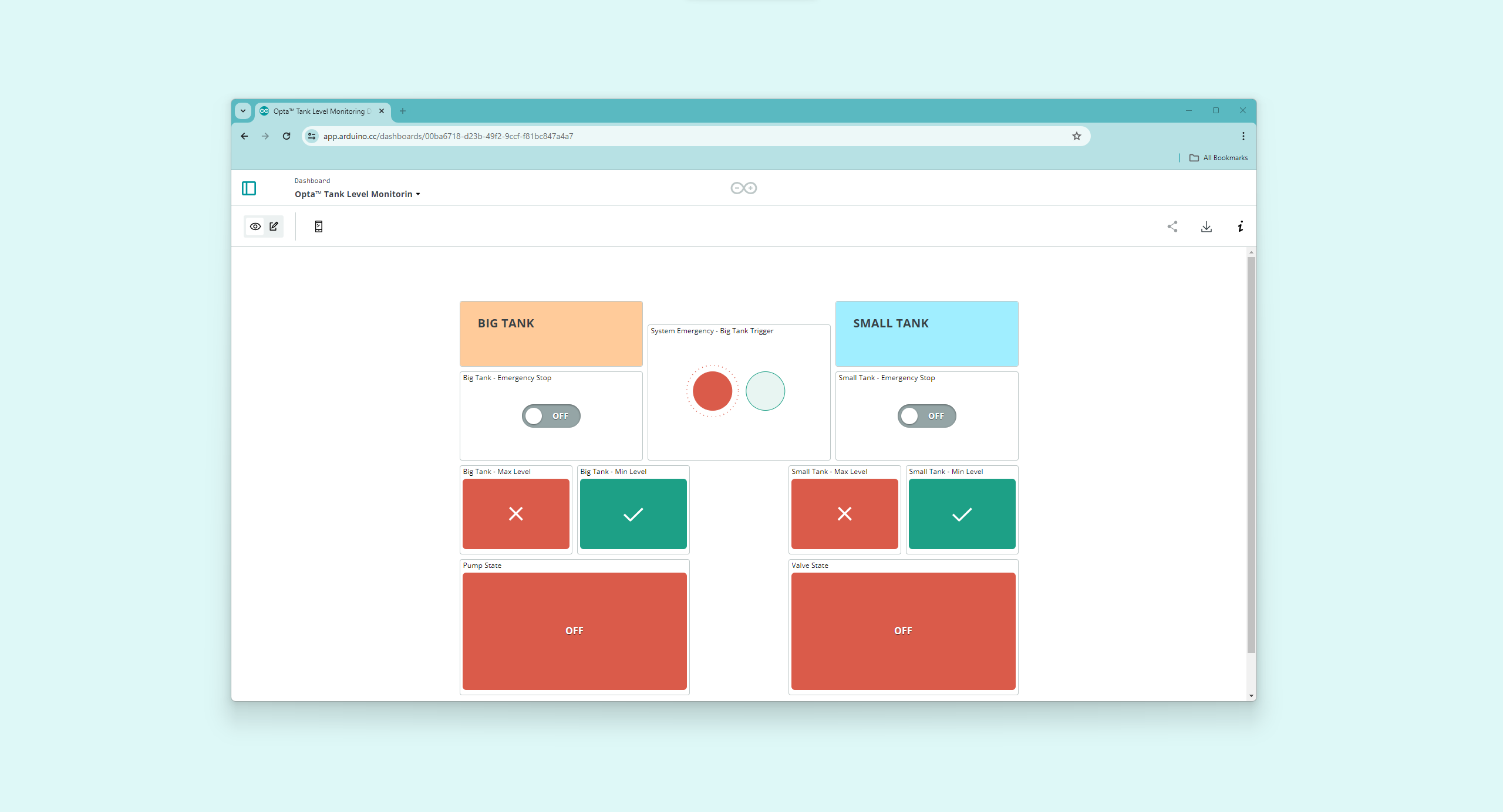
Within Arduino Cloud’s dashboard, the system status of both the tanks can be monitored and the remote actuation is implemented for both the Opta™ devices’ managed tasks. Using this powerful tool, the actuators and emergency stop can be controlled remotely on-demand. The dashboard can also be used to make a simulation, even without the full exact hardware implementation of the application note.
Full Tank Level Monitoring Example
The complete code for the Small and Big Tank’s management implementation with Opta™ can be downloaded here. It is important to know that for both, thingProperties.h is included with its respective variables and is generated automatically with Arduino Cloud. It also contains essential network interface settings, which in this case is configured using the Wi-Fi® network interface.
The Arduino Cloud automatically generates a specialized header file customized to the configured network interface settings and defined variables. It is recommended to avoid manual edits to this file. Network interface settings or variables should be modified through the Arduino Cloud interface.
Opta™ is set up with Wi-Fi® as the network interface for the present application note’s example. Thus, the thingProperties.h file includes settings such as the network SSID and password. The highlighted elements of the code for this configuration are shown below:
For example, in this application note, Opta™ uses Wi-Fi® as its network interface. As a result, the thingProperties.h header incorporates settings like the network SSID and password. Below are the elements of the code for this Wi-Fi® configuration:
//code generated by Arduino IoT Cloud, DO NOT EDIT.

#include <ArduinoIoTCloud.h>
#include <Arduino_ConnectionHandler.h>

const char SSID[]     = SECRET_SSID;    // Network SSID (name)
const char PASS[]     = SECRET_OPTIONAL_PASS;    // Network password (use for WPA, or use as key for WEP)

...

WiFiConnectionHandler ArduinoIoTPreferredConnection(SSID, PASS);
Should Opta™ need to be set up with an Ethernet connection, the thingProperties.h header would contain different parameters, such as IP, DNS, Gateway, and Netmask. The corresponding code highlight for an Ethernet setup would be updated to:
#include <ArduinoIoTCloud.h>
#include <Arduino_ConnectionHandler.h>

const char IP[]      = SECRET_OPTIONAL_IP;
const char DNS[]     = SECRET_OPTIONAL_DNS;
const char GATEWAY[] = SECRET_OPTIONAL_GATEWAY;
const char NETMASK[] = SECRET_OPTIONAL_NETMASK;

...

EthernetConnectionHandler ArduinoIoTPreferredConnection(IP, DNS, GATEWAY, NETMASK);
Conclusion
In this application note, we have learned how to set up the communication between two Opta™ devices using the Modbus RTU protocol, to exchange data, and to build a simple tank-level monitoring system using its I/O ports. We have also learned how to use the Arduino Cloud features to have an on-demand trigger and to monitor the actual tank-level information through a dashboard that displays statistics of the whole system in real-time.
Next Steps
Now that you have learned how to design and build a tank level monitoring system with Opta™, using the Modbus RTU protocol and the Arduino Cloud platform for on demand remote actuation, you can explore the possibilities to scale your projects further, by integrating Opta™ as a part of a manufacturing or maintenance system.