Guides and Tutorials |
Reading a Finder 6M series via Modbus RTU with Finder OPTA in CODESYS
Learn how to configure Finder OPTA in CODESYS to read data from a Finder 6M series via Modbus RTU.
Overview
Finder OPTA is equipped with an RS-485 port that allows communication with devices compatible with the Modbus RTU protocol, such as the Finder 6M series. In this tutorial, we will show step-by-step how to configure Finder OPTA in CODESYS to correctly read data from a Finder 6M series power analyzer.
Goals
- Configure Finder OPTA via Ethernet to read registers from a Finder 6M series in CODESYS
- Read registers from a Finder 6M series via Modbus RTU in CODESYS
Requirements
Before you begin, make sure you have:
- PLC Finder OPTA CODESYS (x1)
- 12W or 25W switching power supply for OPTA(1x)
- Finder 6M series power analyzer (x1)
- Ethernet cable (x1)
- Wire with either specification for RS-485 connection (x2):
- STP/UTP 24-18AWG (Unterminated) 100-130Ω rated
- STP/UTP 22-16AWG (Terminated) 100-130Ω rated
- CODESYS development environment installed with OPTA Configurator plug-in. You can find an installation guide at this link.
- Properly configured network: the PC must communicate correctly with Finder OPTA via Ethernet. Configuration guide is available at this link.
To follow this tutorial, you will need to connect the Finder 6M series power analyzer to the power supply and provide a suitable load. You will also need to power Finder OPTA with a 12-24VDC/500mA power supply and properly configure the RS-485 serial connection. The diagram below shows the correct configuration of the connections between Finder OPTA and the Finder 6M series.

The Modbus configuration of the Finder 6M series is determined by the position of the DIP switches, as indicated on page 6 of the user manual. In this tutorial the expected communication parameters are:
- Modbus address:
1. - Baudrate:
38400.
We can set these values by setting both DIP switches of the Finder 6M series to the UP position, as shown in the figure below.

Instructions
Creating a CODESYS Project
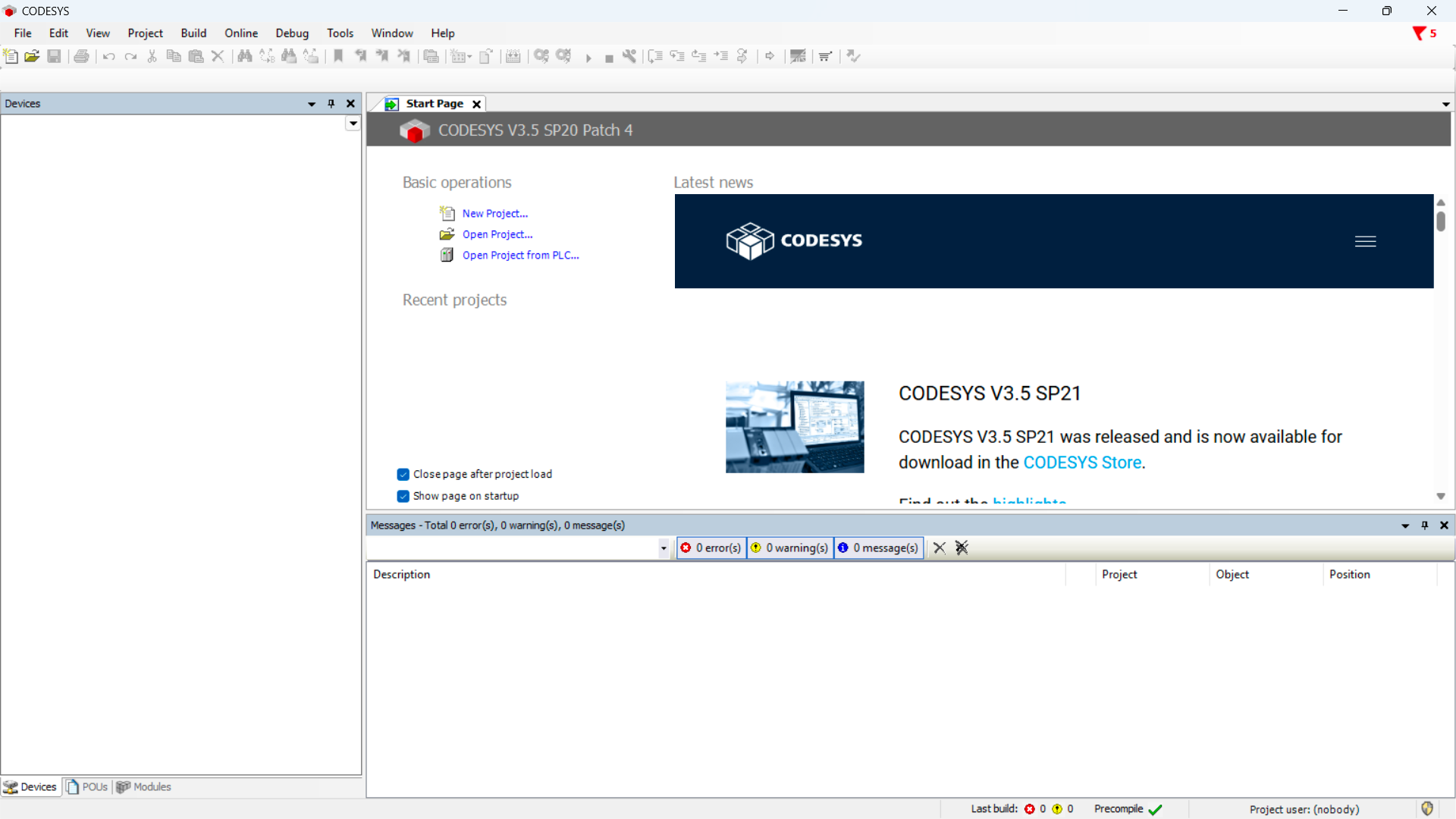
Open CODESYS.
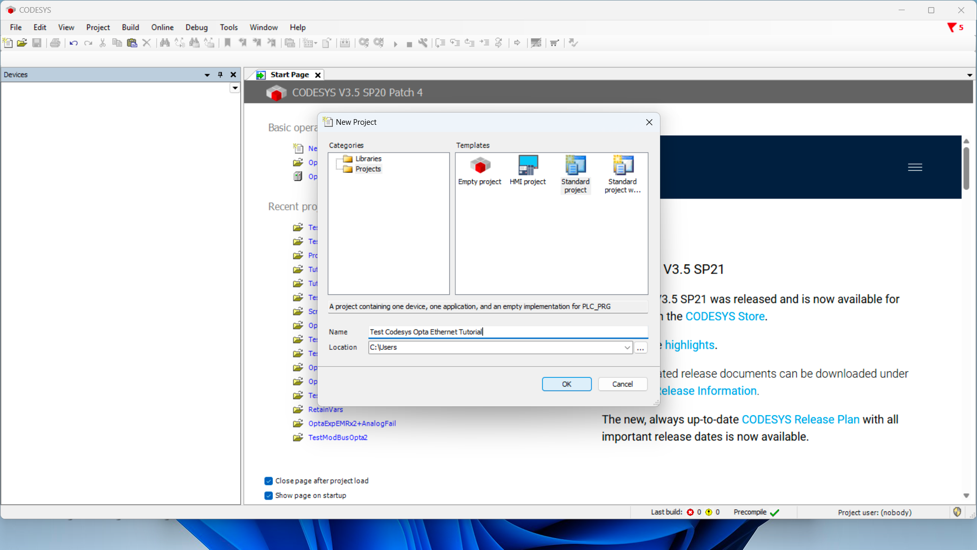
Create a new project and choose Standard Project.
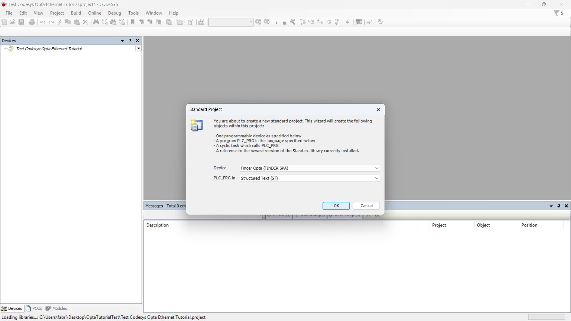
Make sure the device is Finder Opta, then select the programming language (we will use ST).
Identifying Finder OPTA via Ethernet
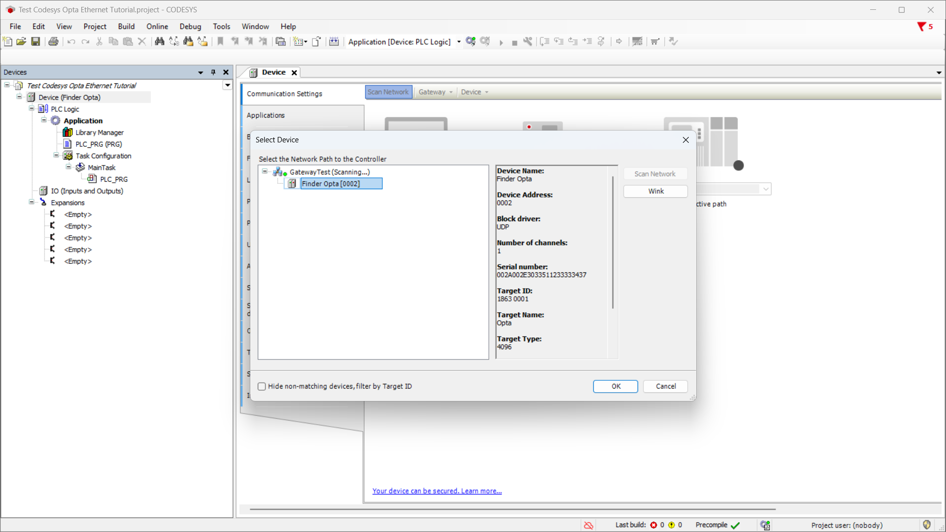
Now double-click on the Device (Finder Opta) entry in the Devices menu, a tab will open as shown below.
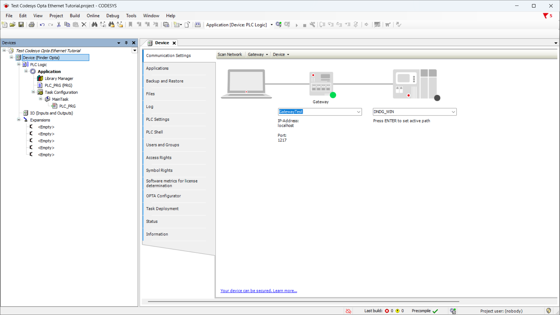
Press the Scan Network button and ensure Finder OPTA device appears under the Gateway, then press OK.
Modbus Configuration
At this stage, we configure the RS-485 port and Modbus protocol parameters to ensure Finder OPTA can communicate with the Finder 6M series.
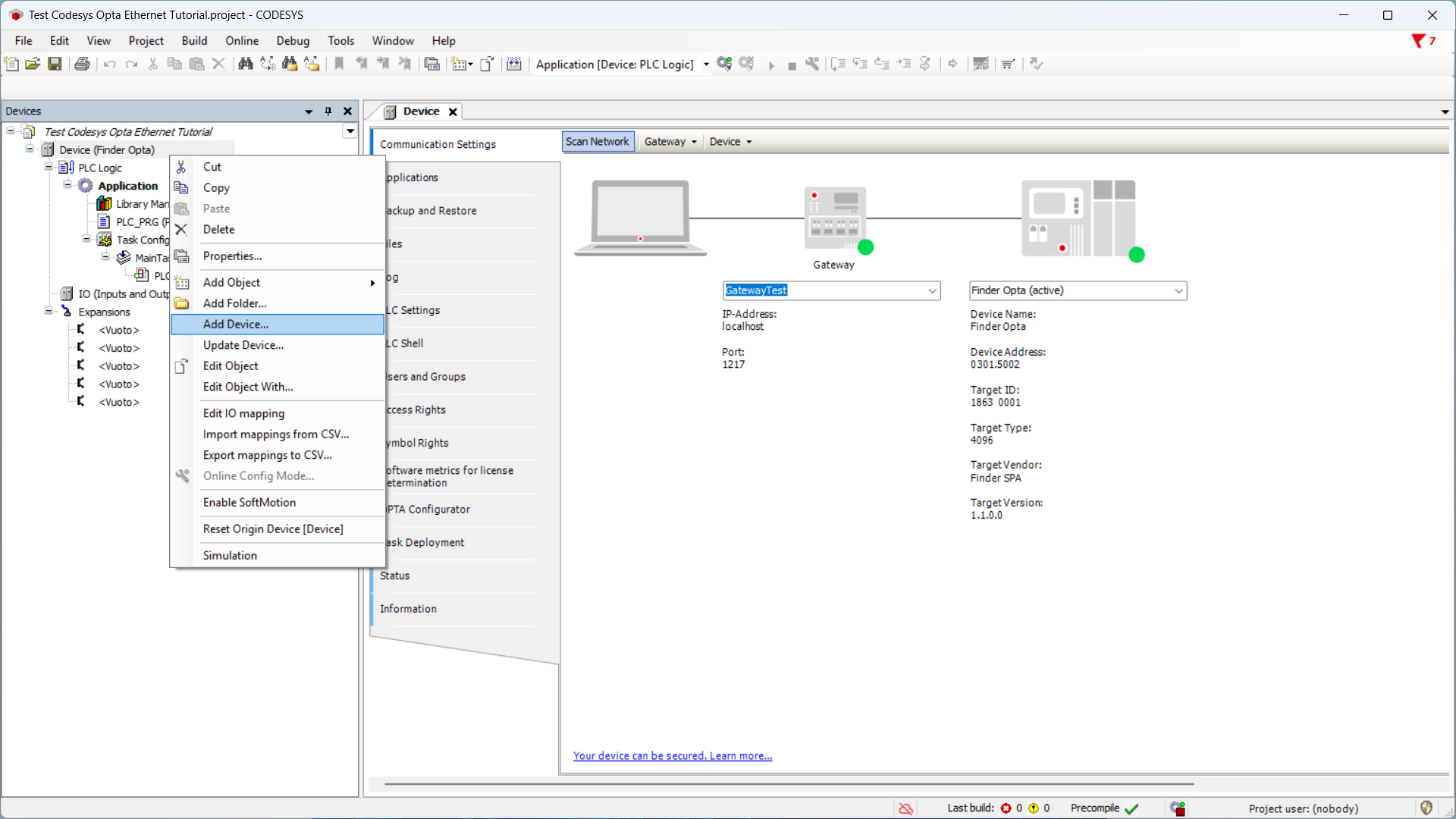
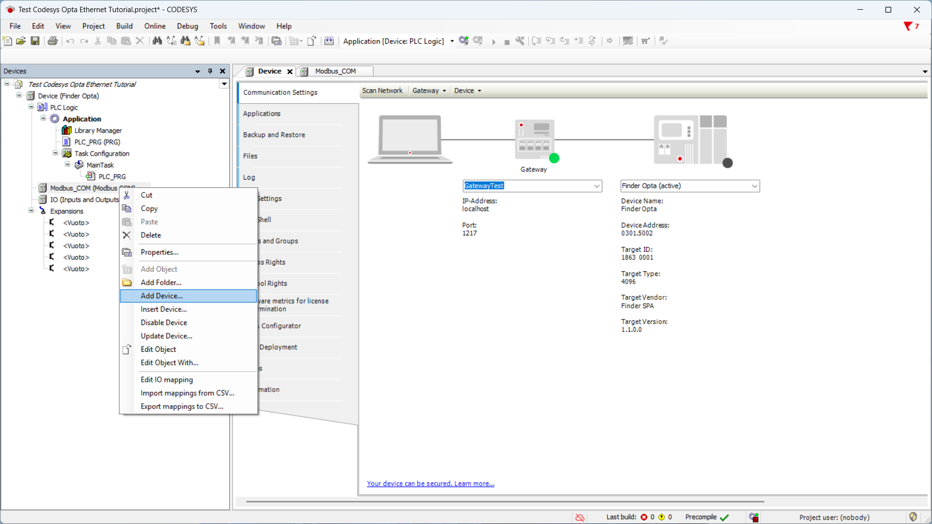
Right-click on Device (Finder Opta) and select Add device....
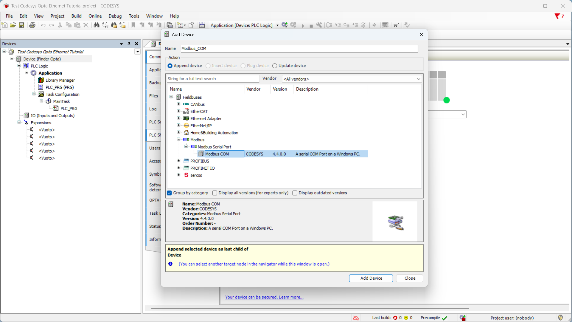
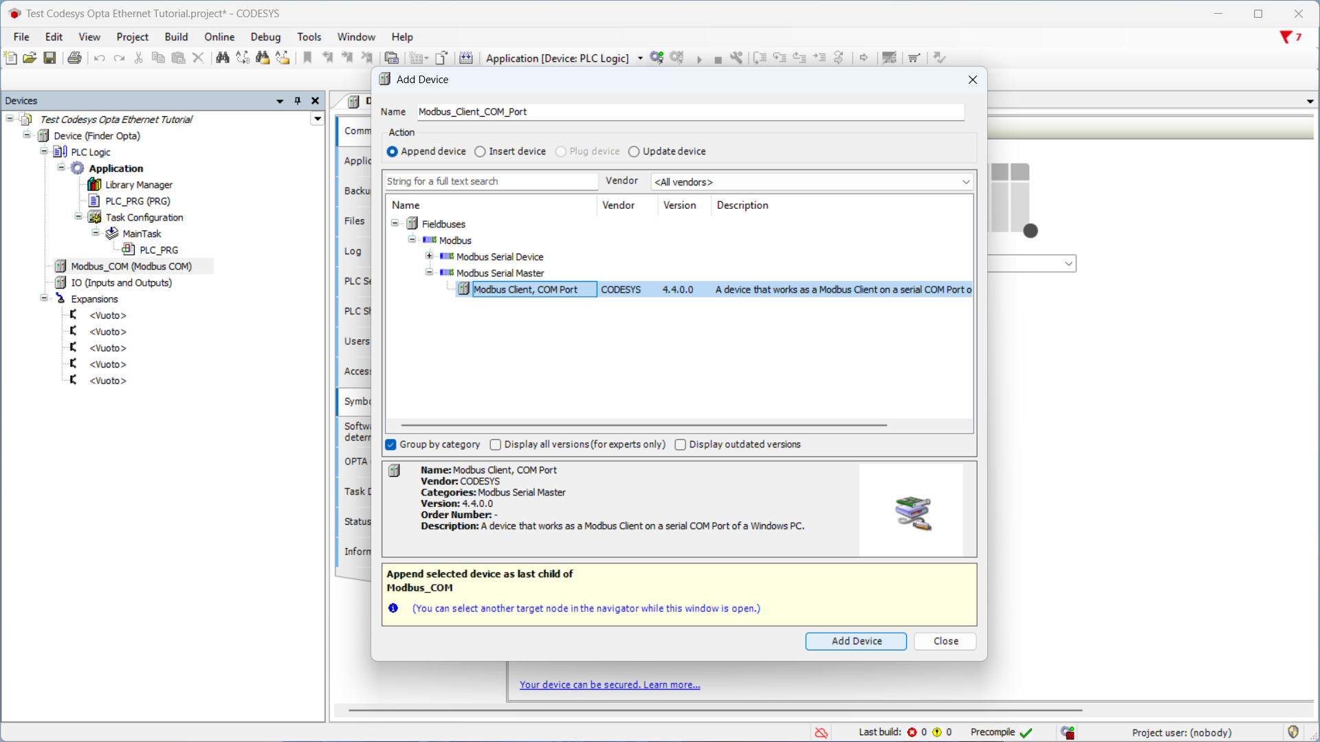
Now configure the Modbus RTU protocol on the RS-485 port of Finder OPTA. From the list select Modbus COM Port and click Add device.
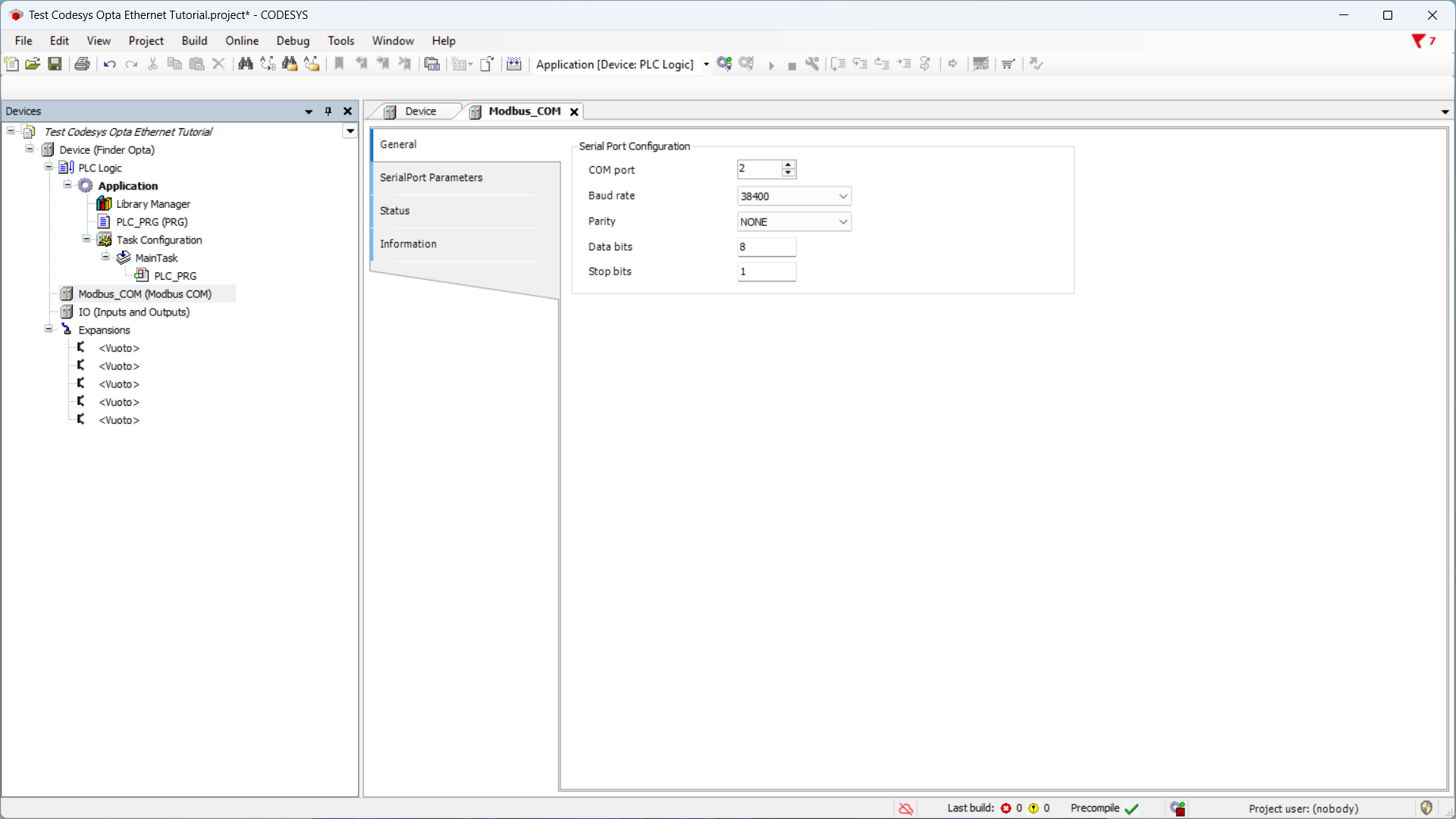
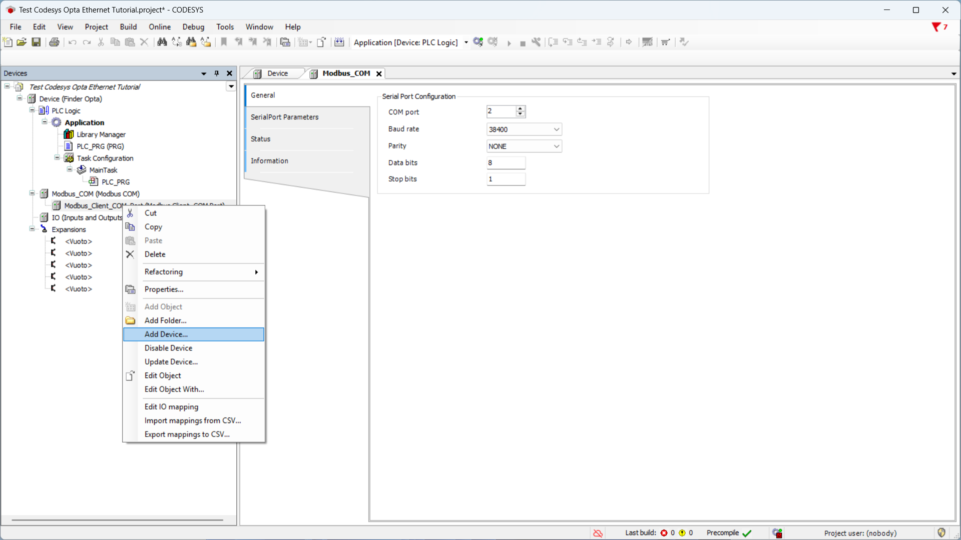
Now set the serial port configuration values as follows:
- COM port:
2, i.e., the RS-485 port of Finder OPTA. - Baud rate:
38400. - Parity:
NONE. - Data bits:
8. - Stop bits:
1.
After setting the serial port values, right-click on Modbus_COM_Port(Modbus COM Port) and then on Add device.
From the list select Modbus Client, COM Port and click Add device. In this way you add a Modbus client communicating on the previously configured serial port, i.e. the Finder 6M series.
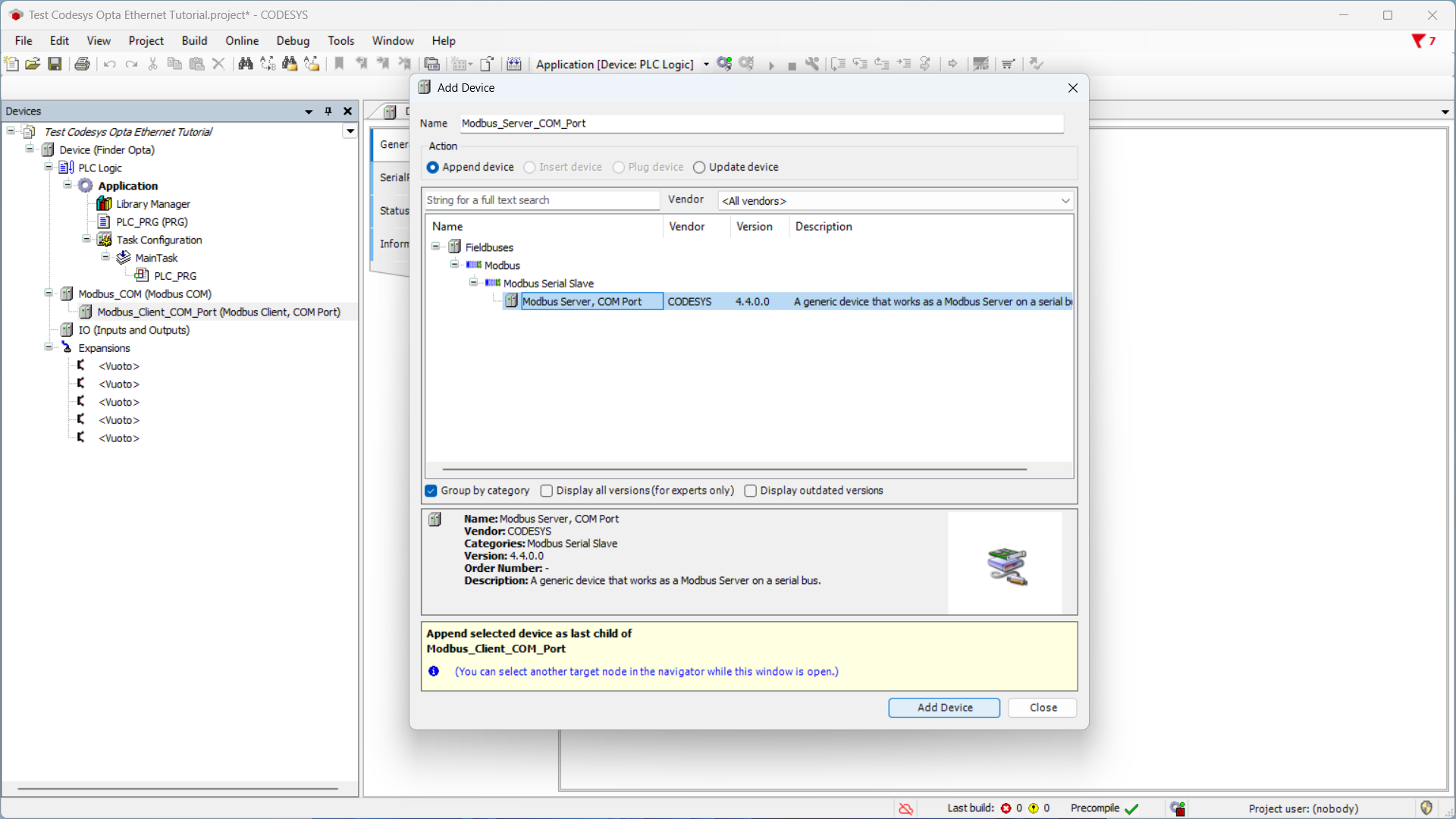
Then right-click on the newly added item Modbus_Client_COM_Port(Modbus Client, COM Port) and click Add device.
Select Modbus Server, COM port, then Add device to specify that the Finder 6M serie will act as server, while the Finder OPTA will act as client.
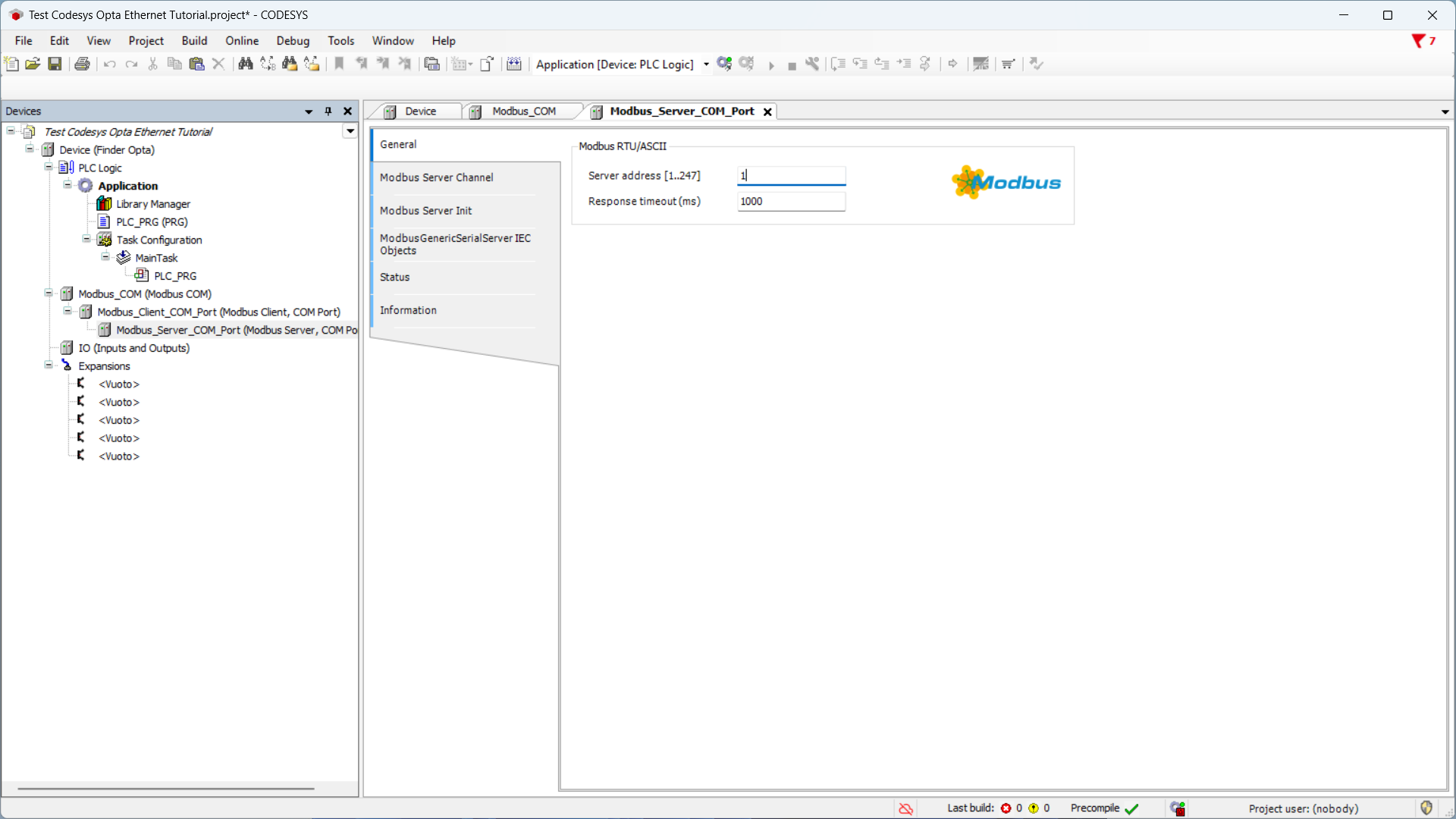
Now click on the newly added item and make sure the Server address is set to 1, the Modbus address of the Finder 6M series.
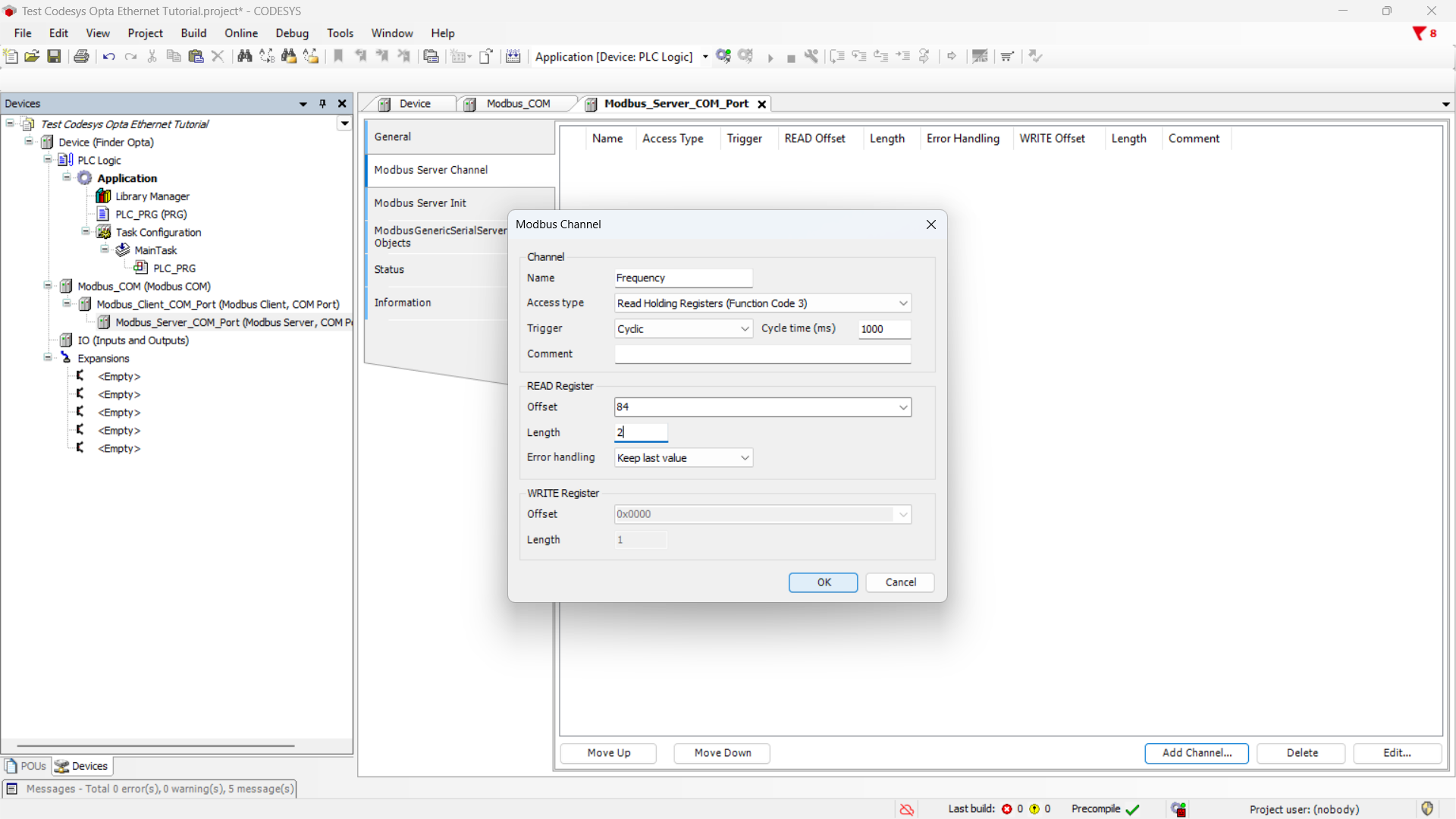
Finally, we configure a Modbus server channel, meaning we set the parameters that will be used by the program to read from the Finder 6M series. In the same screen click on Modbus Server Channel then on Add channel at the bottom right. In this tutorial we read the frequency value from the Finder 6M series. As defined in the device technical manual, the frequency value is stored in Input Registers 40085 and 40086 in float format. Therefore, set the channel values as follows:
- Name:
Frequency. - Access type:
Read Input Registers (Function code 4). - Trigger:
Cyclic. - Cycle time:
1000, meaning one read per second. - Offset:
84. - Length:
2. - Error handling:
Keep last value.
The Finder 6M series technical manual counts addresses starting from 1 while CODESYS starts from 0. For this reason, to access Input Register 40085, we set the offset to 84.
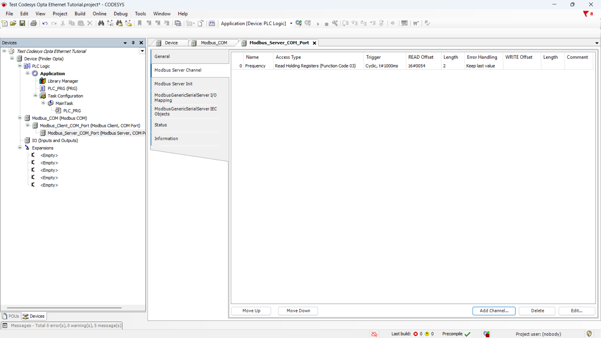
After pressing OK, you will see the summary of the newly configured channel.
Preparing the ST Program
Now we write the ST program that reads the frequency value.
This program directly accesses the variable’s memory address and interprets the content as a float value. This step is essential to obtain the actual measurement stored in the device and transform it into a readable and usable format. In CODESYS, the float format is denoted as REAL.
In the sidebar, click on PLC_PRG (PRG).
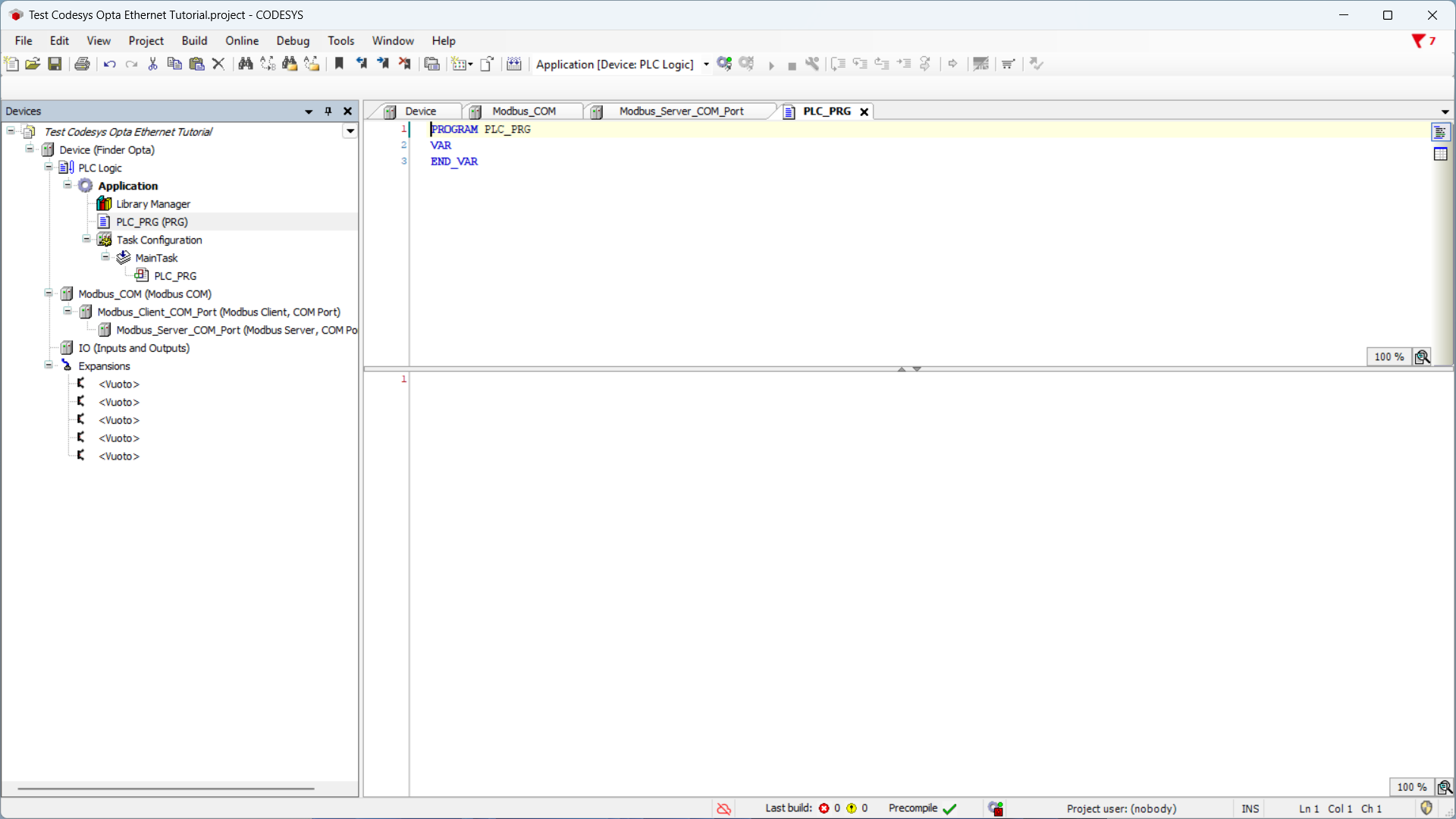
At the top of the editor – section dedicated to variables declaration – insert the following code:
PROGRAM PLC_PRG
VAR
    words: ARRAY[0..1] OF WORD;
    ptr: POINTER TO REAL;
    frequency: REAL;
END_VAR
At the bottom of the editor – section dedicated to program logic – insert the following code:
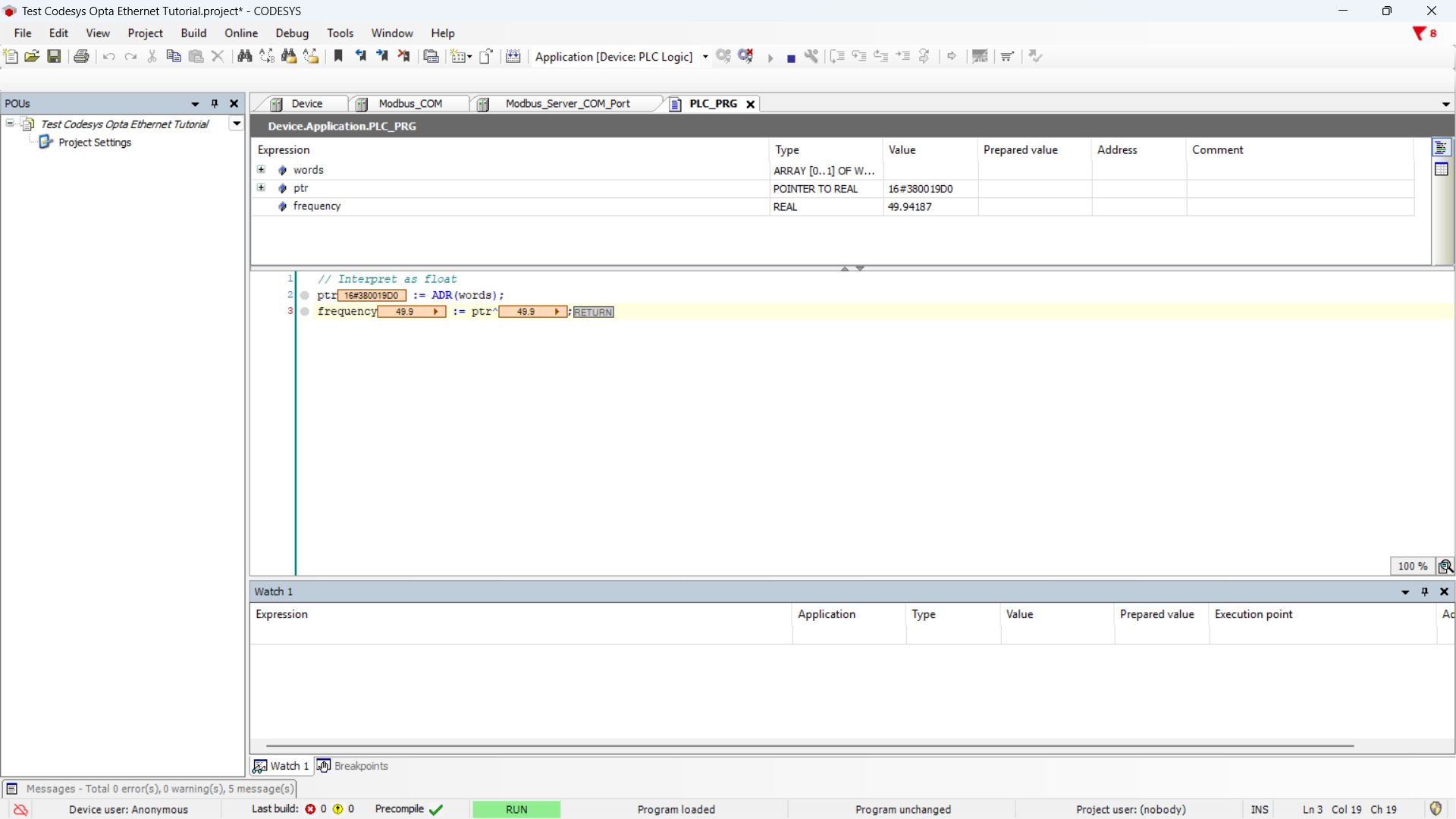
// Interpret as float
ptr := ADR(words);
frequency := ptr^;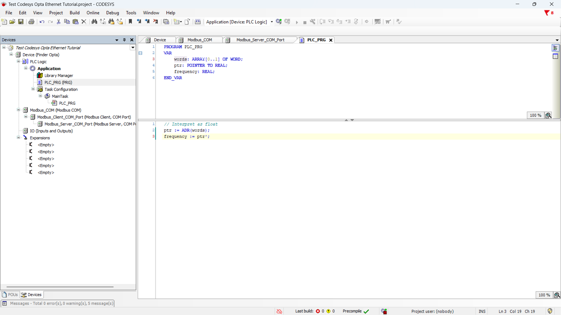
Now it is necessary to associate the program variables with the Modbus channel, so that the variables contain the values read from the channel.
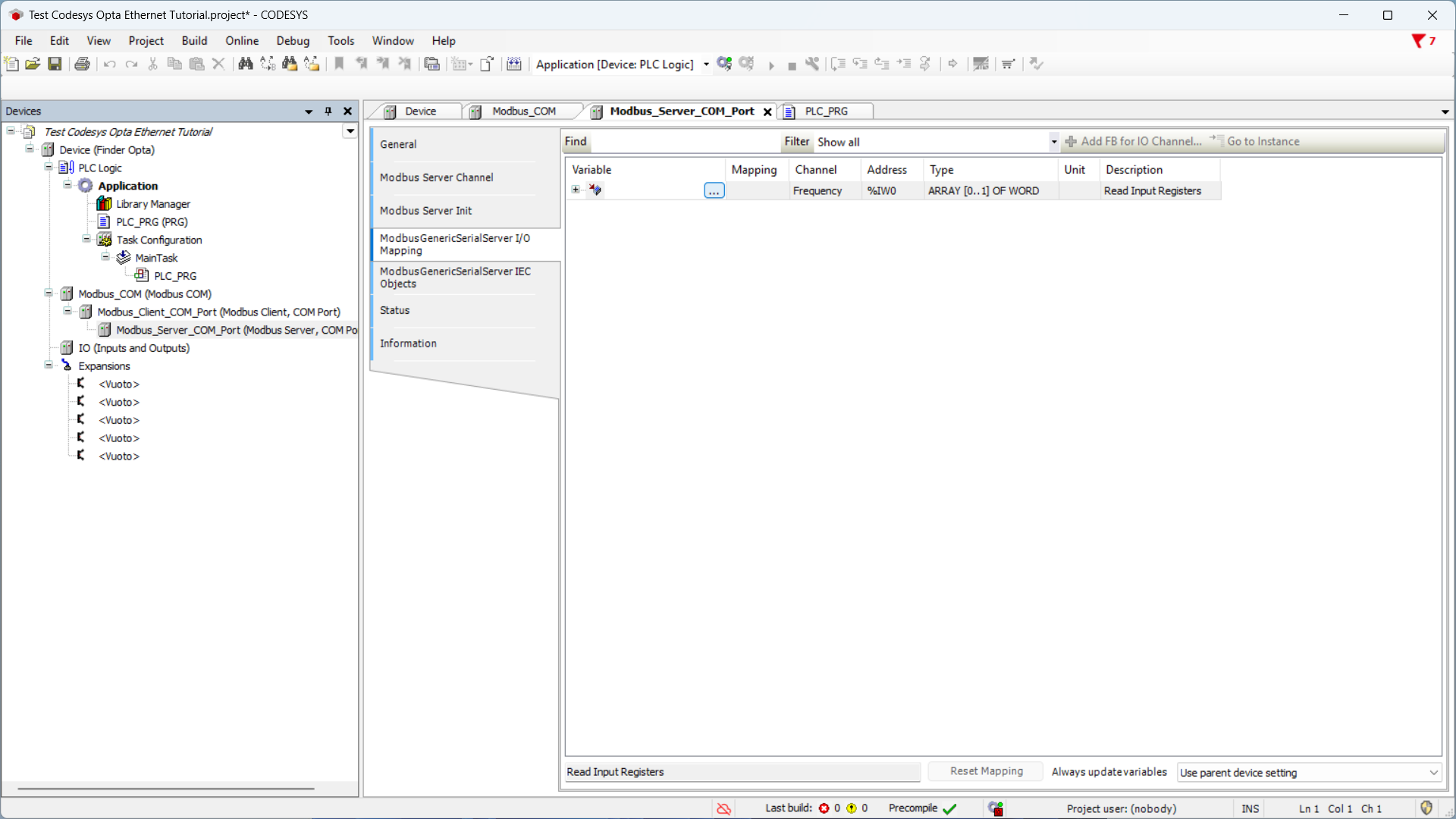
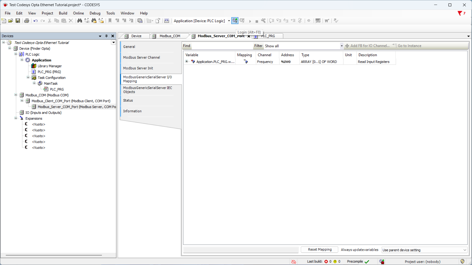
In the sidebar, double-click on Server_Modbus_COM_port. Now click on the section ModbusGenericSerialServer mapping I/O and in the table double-click the Variable cell to display the option button.
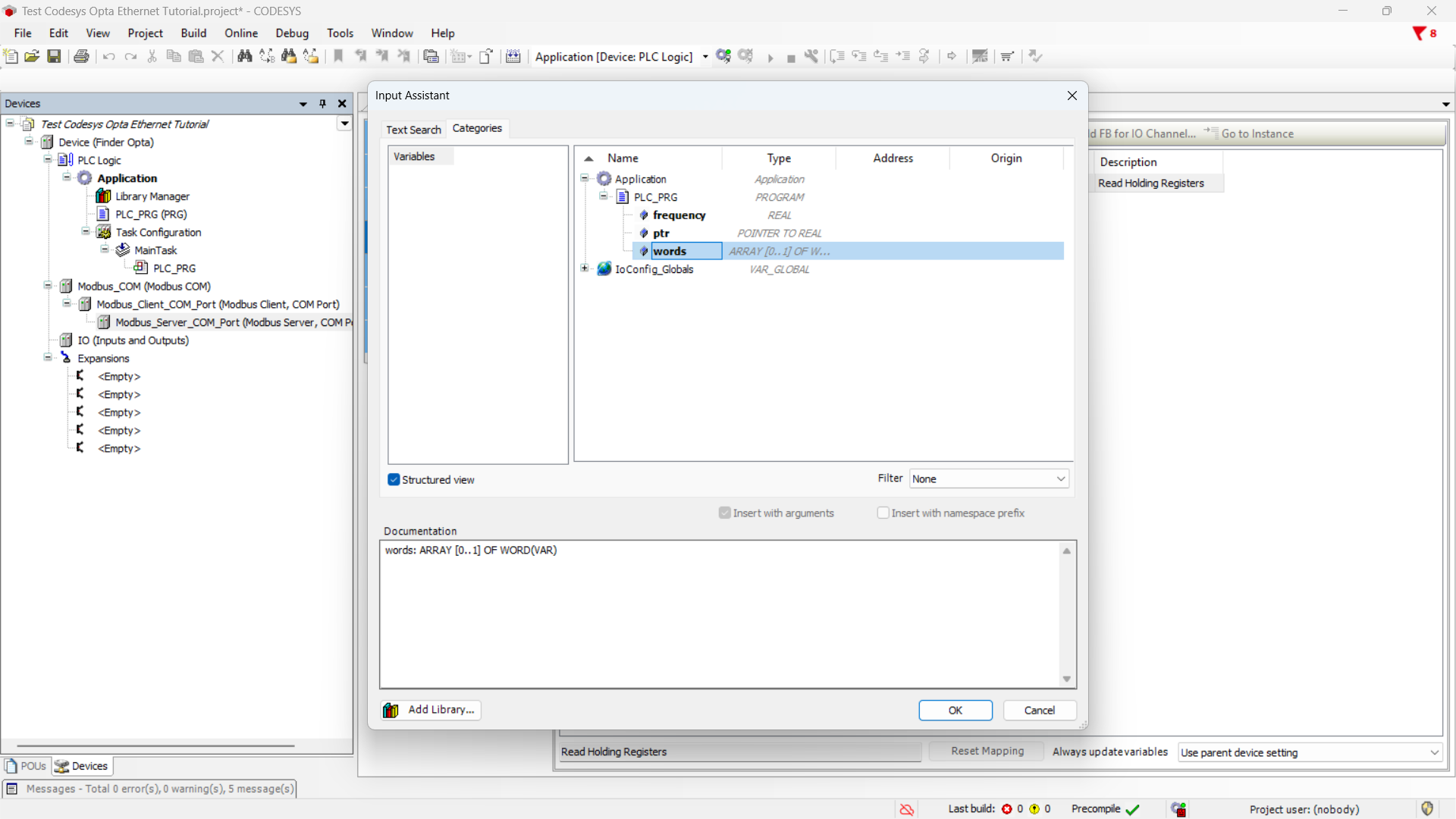
Click the options button to display the list of variables, expand Application and then PLC_PRG to access the variables previously defined in the ST program. Now click on the words variable and press OK to assign it to the Frequency channel.
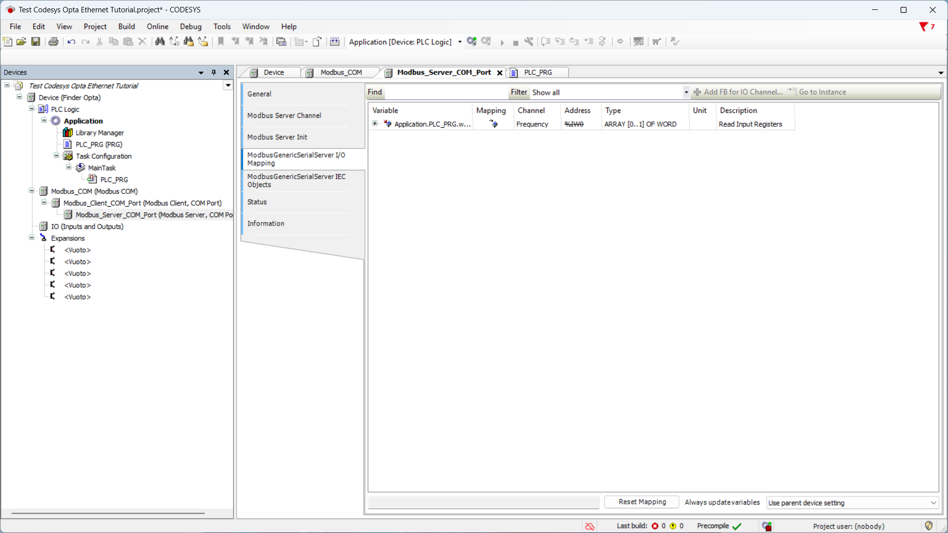
The summary shows the variable assigned to the Frequency channel. From now on, the variable words contains the bytes read from the registers of the Finder 6M series, representing the frequency value measured by the device. It’s our ST program that transforms these bytes in float.
Uploading the Program to Finder OPTA
At this stage, we download the program and the hardware configuration to Finder OPTA, so that it executes the code we just wrote, returning the frequency value read by the Finder 6M series.
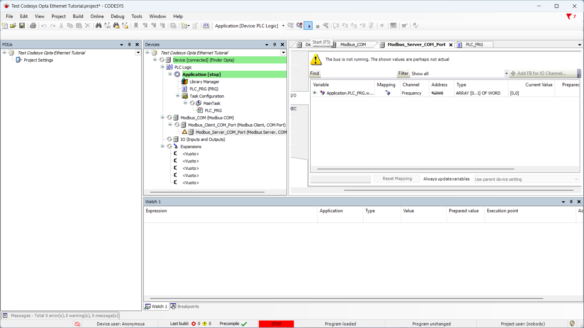
Download the program and configuration to the device by pressing the green button at the top labeled Login.
Once the download is over, the program will be downloaded on Finder OPTA. Execute it by pressing the Start button.
The PLC_PRG tab displays the frequency value in real time, stored in the frequency variable, in this case 49.94 Hz.
Conclusions
By following these steps, you have performed a Modbus RTU read from the registers of a Finder 6M series using Finder OPTA in CODESYS.
If you encounter issues, verify that the devices are wired correctly and that the Modbus parameters are configured as specified in the tutorial.