Guide and Tutorial |
Introduction
In this application note, you will learn how to control the temperature of an industrial tank using a PT100 RTD sensor connected to a Portenta Machine Control and an Opta™ that will be responsible for the tank temperature control.
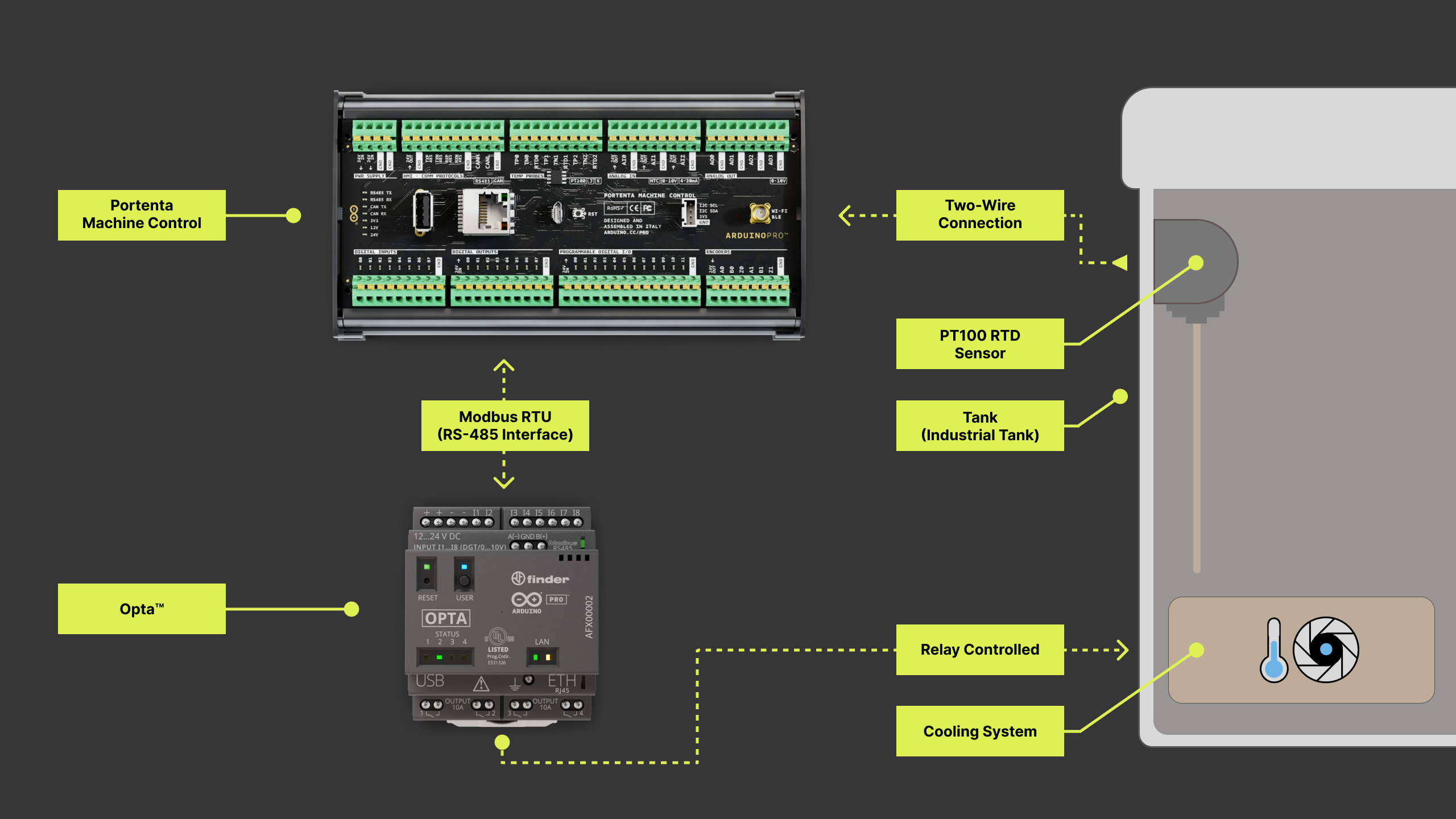
The system will send the temperature values from the Portenta Machine Control to the Opta™ using Modbus RTU over the RS-485 interface. The Opta™ will subsequently use these values and control the reservoir temperature accordingly.
Goals
- Establish connection between Portenta Machine Control and Opta™ using Modbus RTU
- Control the temperature of a tank of industrial category
- Learn about Modbus RTU and RS-485 of how it can be used in different professional applications
- Learn more about PLC IDE and how to use it to create Modbus communications in industrial environments
Hardware and Software Requirements
Hardware Requirements
- Portenta Machine Control (x1)
Opta™ PLC with RS-485 support: Opta™ Plus, or Opta™ Advanced (x1) - Micro-USB cable (x1)
- USB-C® cable (x1)
- PT100 RTD (x1)
Software Requirements
- The Arduino PLC IDE
- Portenta Machine Control – PLC IDE Activation
- Opta™ – Set up with PLC IDE
- You can directly download the Arduino PLC IDE Projects and extract them in your workspace
It is recommended to read Connect RTD/Thermocouple to the Portenta Machine Control tutorial before continuing to follow the present tutorial.
Temperature Sensor
In this tutorial, a Two-wire PT100 RTD is used, but you can also use a Three-wire RTD or a thermocouple depending on your requirements or preferences. You can learn more about the differences between these temperature sensors and how to connect them to the Portenta Machine Control following the previously mentioned tutorial. It is recommended to read this tutorial to learn the basics about the temperature sensors introduced earlier.
Connections
To establish communication between Opta™ and the Portenta Machine Control, we will do it through Modbus RTU communication using the RS-485 interface. The following table shows the required connection between two devices to achieve this communication:
| Opta™ | Portenta Machine Control |
|---|---|
| A(-) | TXP 485 |
| B(+) | TXN 485 |
| GND | GND |
The Portenta Machine Control has support for full-duplex communication, while Opta™ specifically supports half-duplex communication. Due to this reason, the TXP and TXN RS-485 pins will be used only on the PMC as shown in the following image:
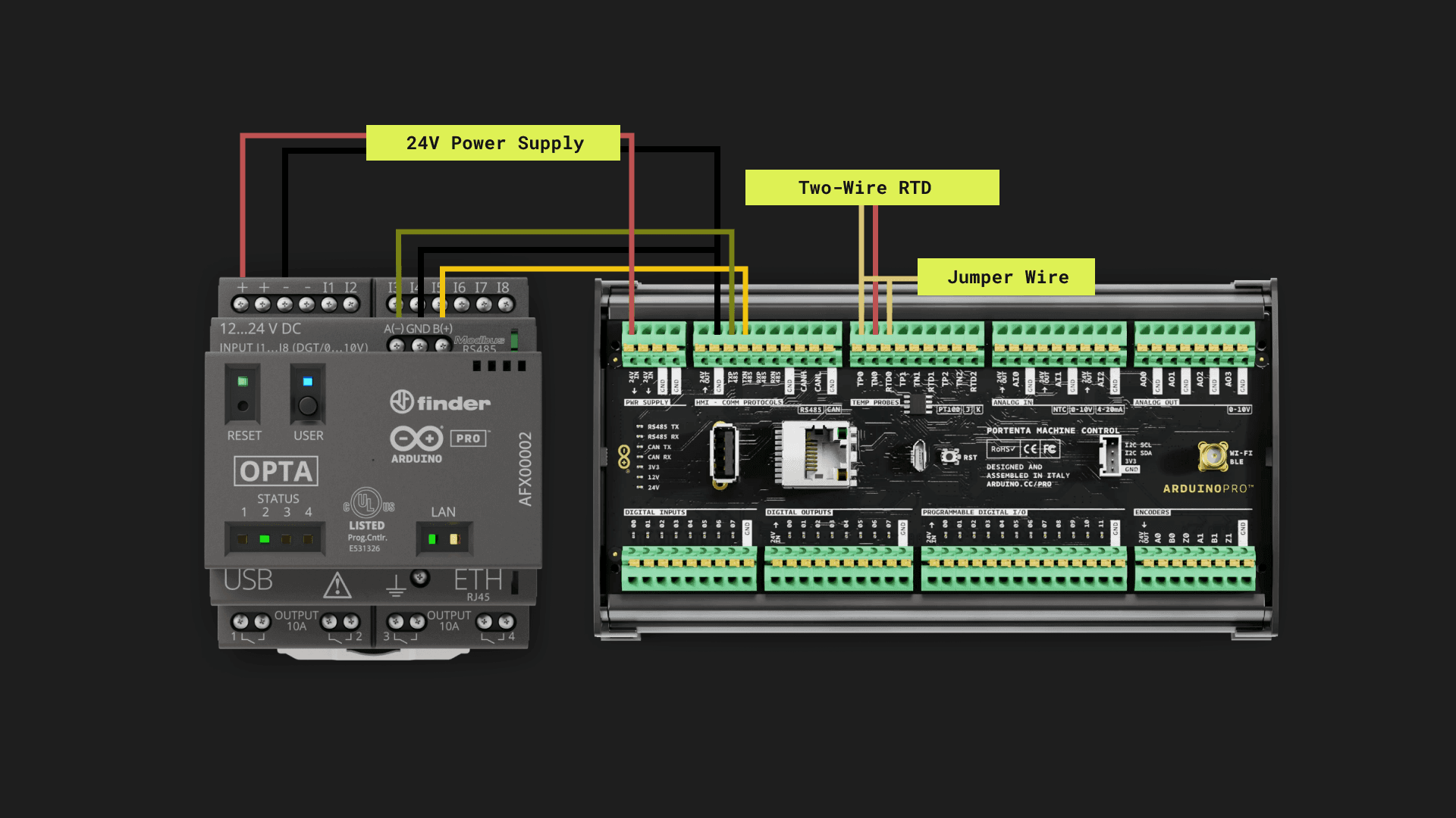
Because Opta™ has no internal termination resistors, it must be installed per the Modbus protocol specification adding termination resistors. Also, if you experience inconsistent data transmission using Opta™ with other Modbus RTU compatible devices, please try again by inverting the A(-) and B(+) lines.
PLC IDE
To enable this example, you will need to create two PLC IDE projects. One project will be for the Portenta Machine Control, which will act as a Server in the Modbus RTU communication, while the other project will set the Opta™ to behave as the Client.
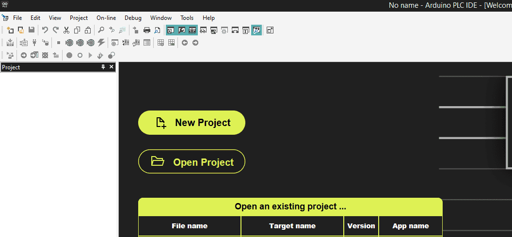
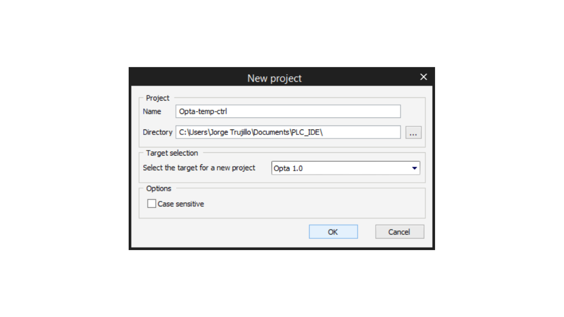
To create a project, open PLC IDE and click on New Project:
Portenta Machine Control Project
Create the PMC Project
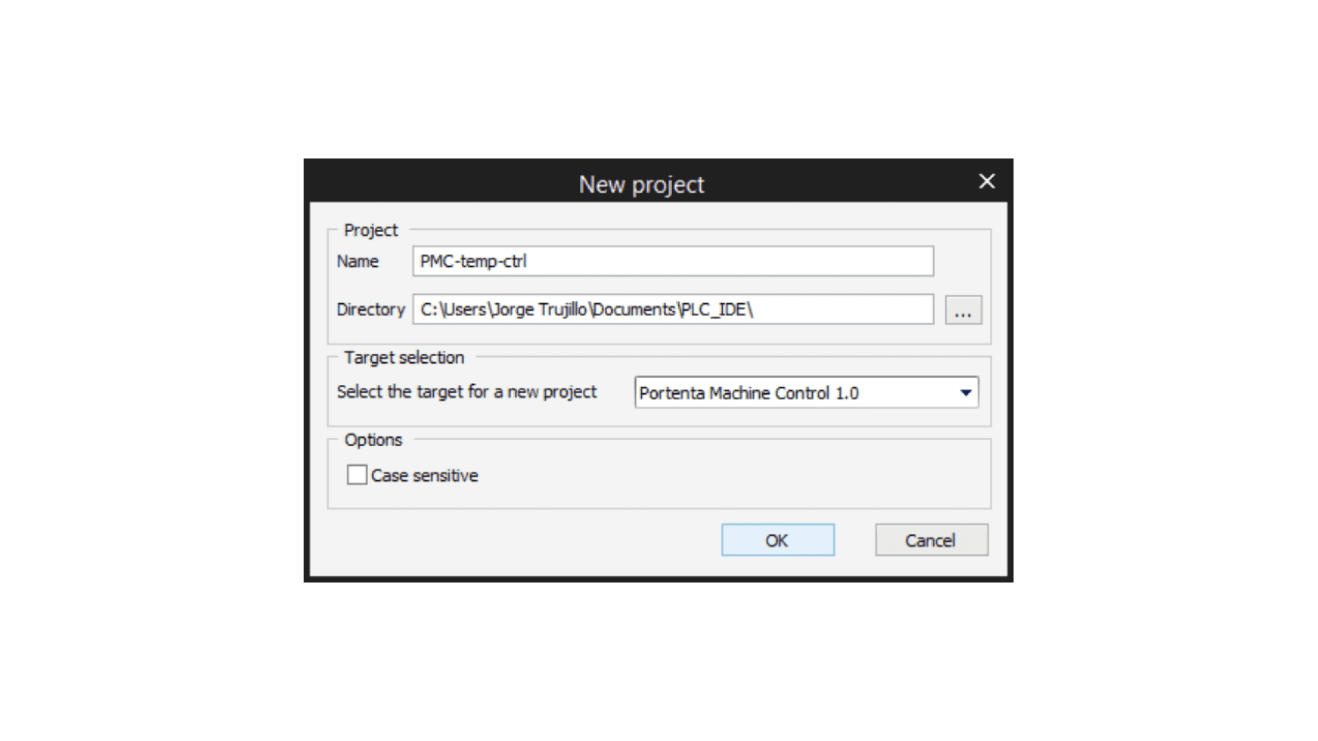
After clicking on New Project in the previous step, a window will appear. Set the name of your choice for the project and select Portenta Machine Control 1.0 on the Target Selection:
Modbus Server Configuration
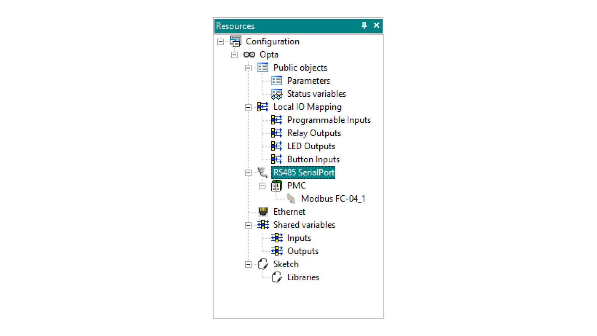
Once created, you will configure the Modbus RTU connection through the RS-485 serial port. To do this, go to the resources window and double-click on RS485 SerialPort. If you can’t see the Resources tab, try going to View > Tool windows > Resources.
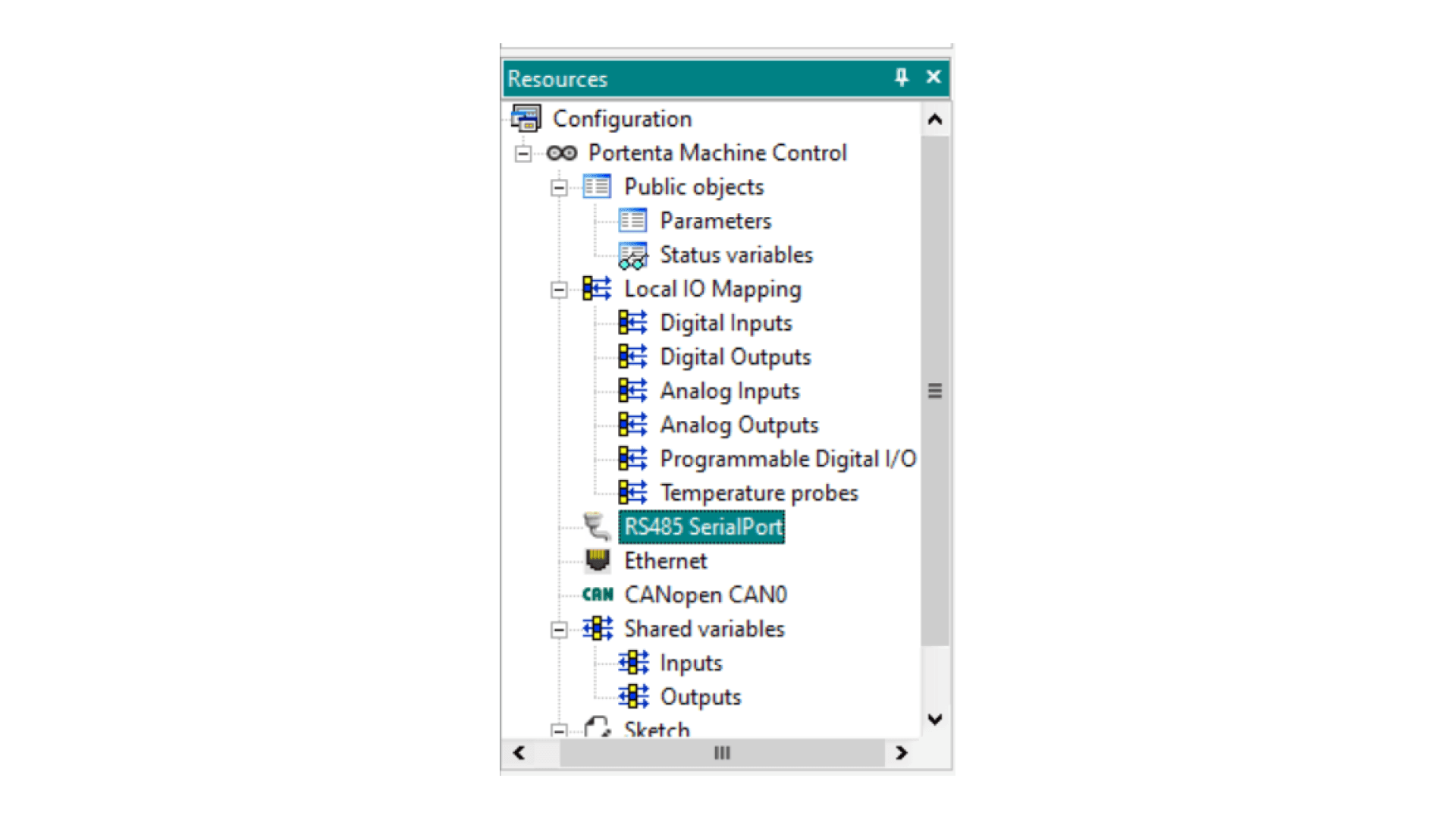
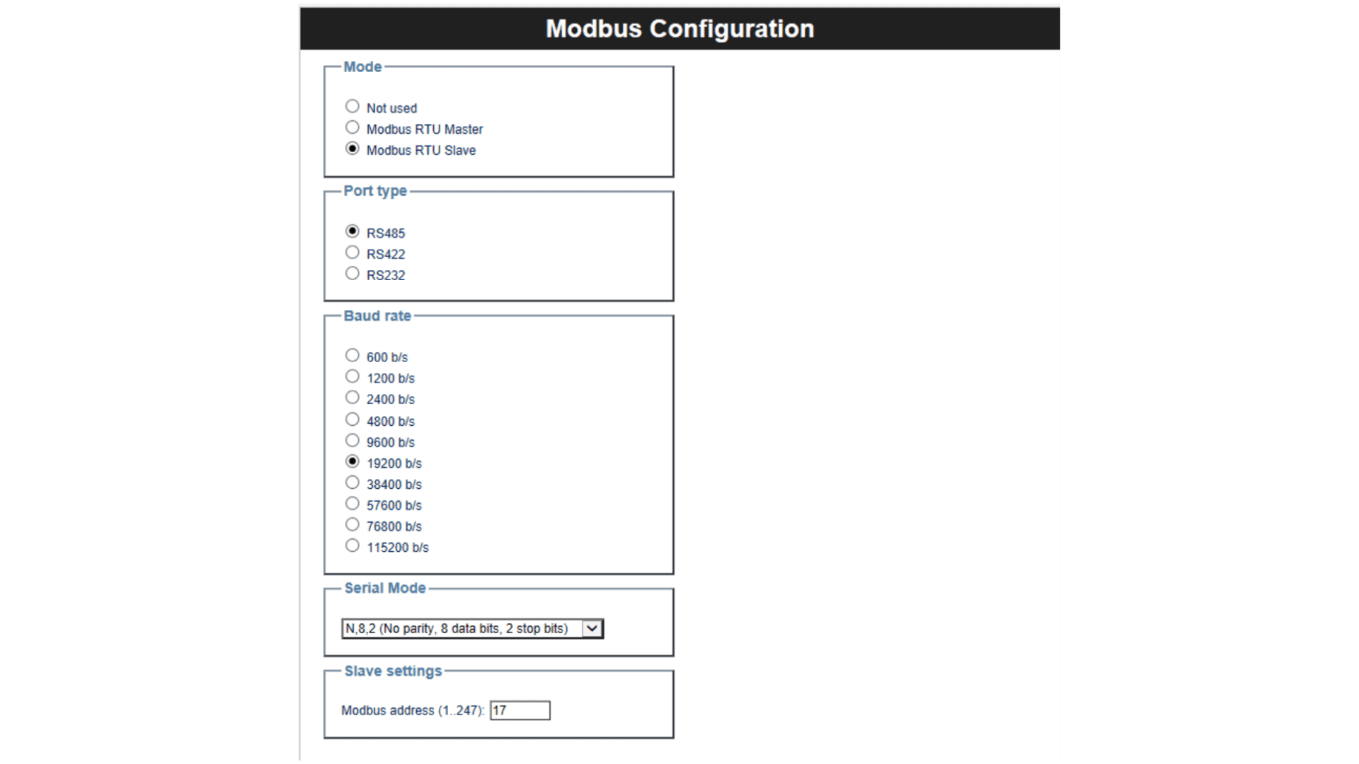
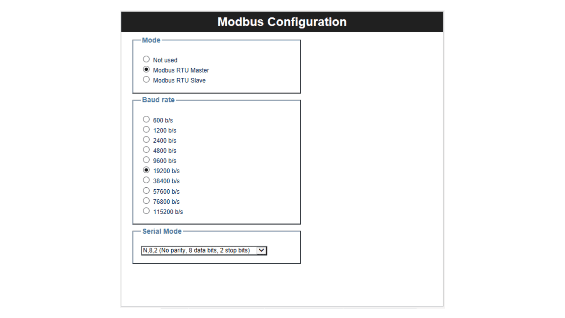
On the Modbus Configuration window, set the following parameters to configure Portenta Machine Control as a Server:
- Mode: Modbus RTU Slave
- Port Type:
RS485 - Baud rate: 19200 b/s
- Serial Mode: N,8,2 (No parity, 8 data bits, 2 stop bits)
- Modbus address: 17
In this case, Modbus Server address is set as 17, but you can define one address in the 1 ... 247 range. Your Modbus RS-485 Server configuration should look like this:
Do not forget the configured Modbus address, as you will need it in the future.
You will now create the variable that will be sent through Modbus RTU. To do this, go to the Resources window and double-click on Status variables:
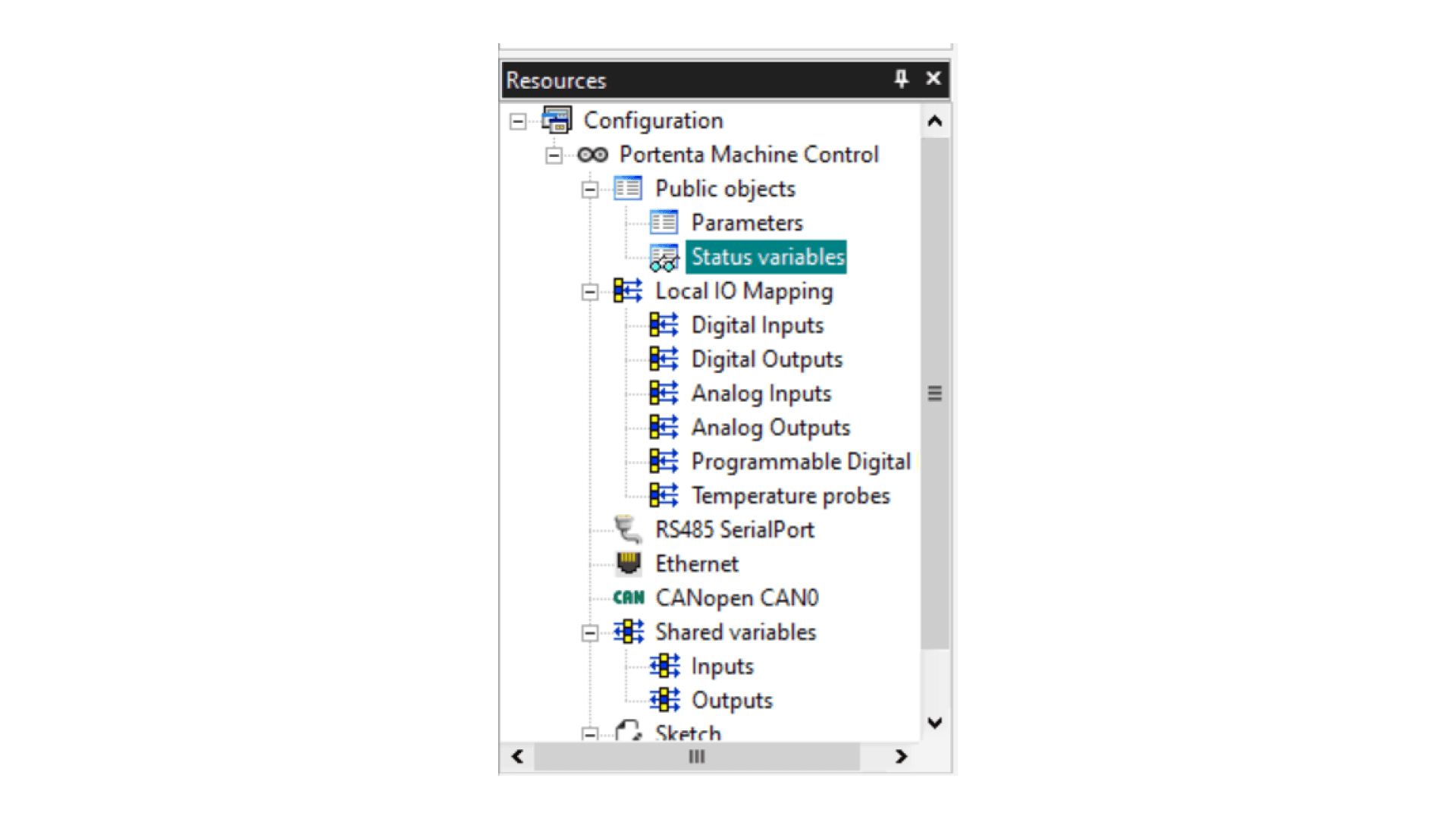
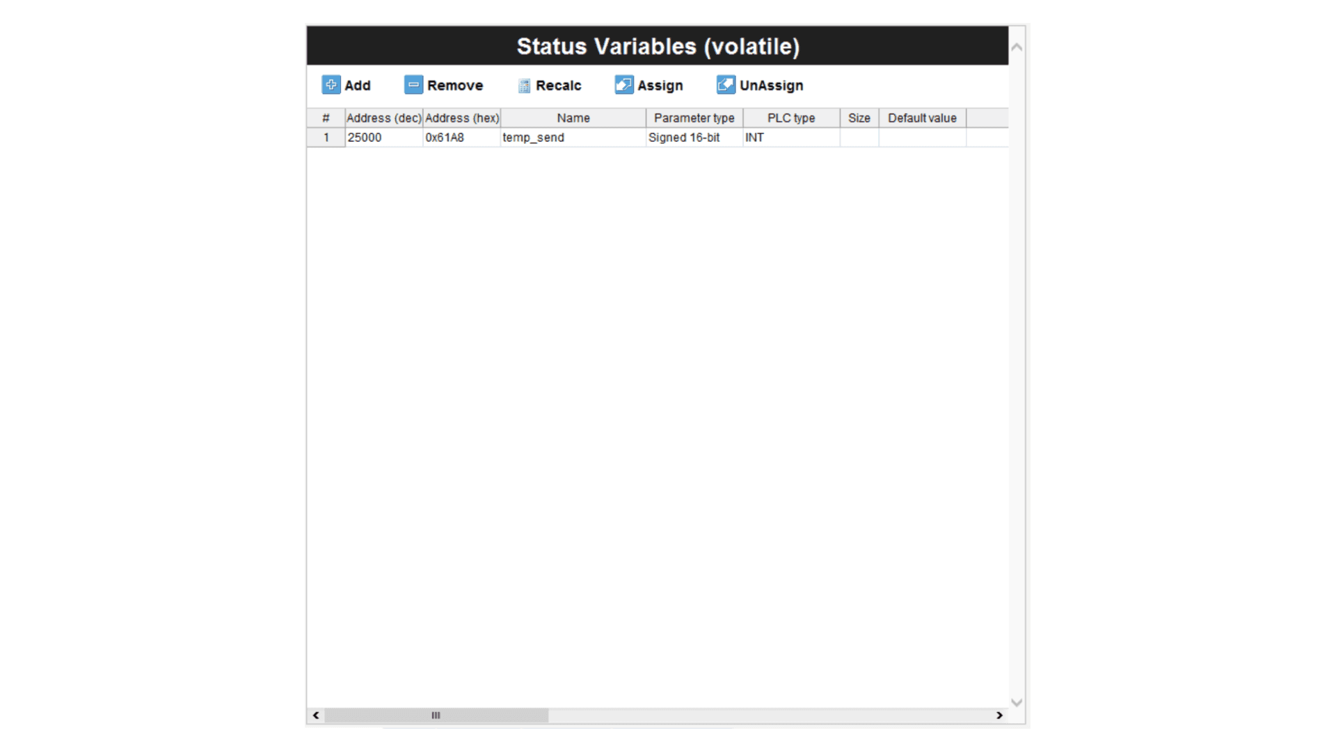
A Status Variables (volatile) window will appear. Click on the Add button and set the following parameters:
- Address: 25000
- Name: temp_send
- PLC type: INT
If everything is correct, it should look like in the next image:
This is all the necessary configuration on the server side. In the next step, you will configure the temperature sensor to be paired with Portenta Machine Control.
Temperature Sensor Configuration
We need to read the values of the temperature sensor. In this case, we are using a PT100 RTD as explained in the Connect RTD/Thermocouple to the Portenta Machine Control tutorial, but you can also use a Three-wire RTD or a Thermocouple depending on what you need.
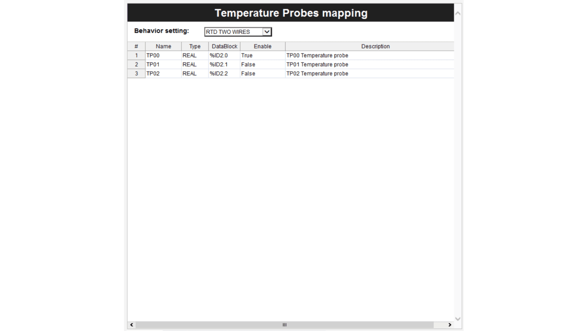
To configure the temperature sensor, in the Resources window, double click on Temperature probes and select the Behavior setting depending on the sensor you are using and also the TPXX where the sensor is connected.
In this case, we are using an RTD TWO WIRES connected to the TP00, so we will set the Enable option as True shown in the following image:
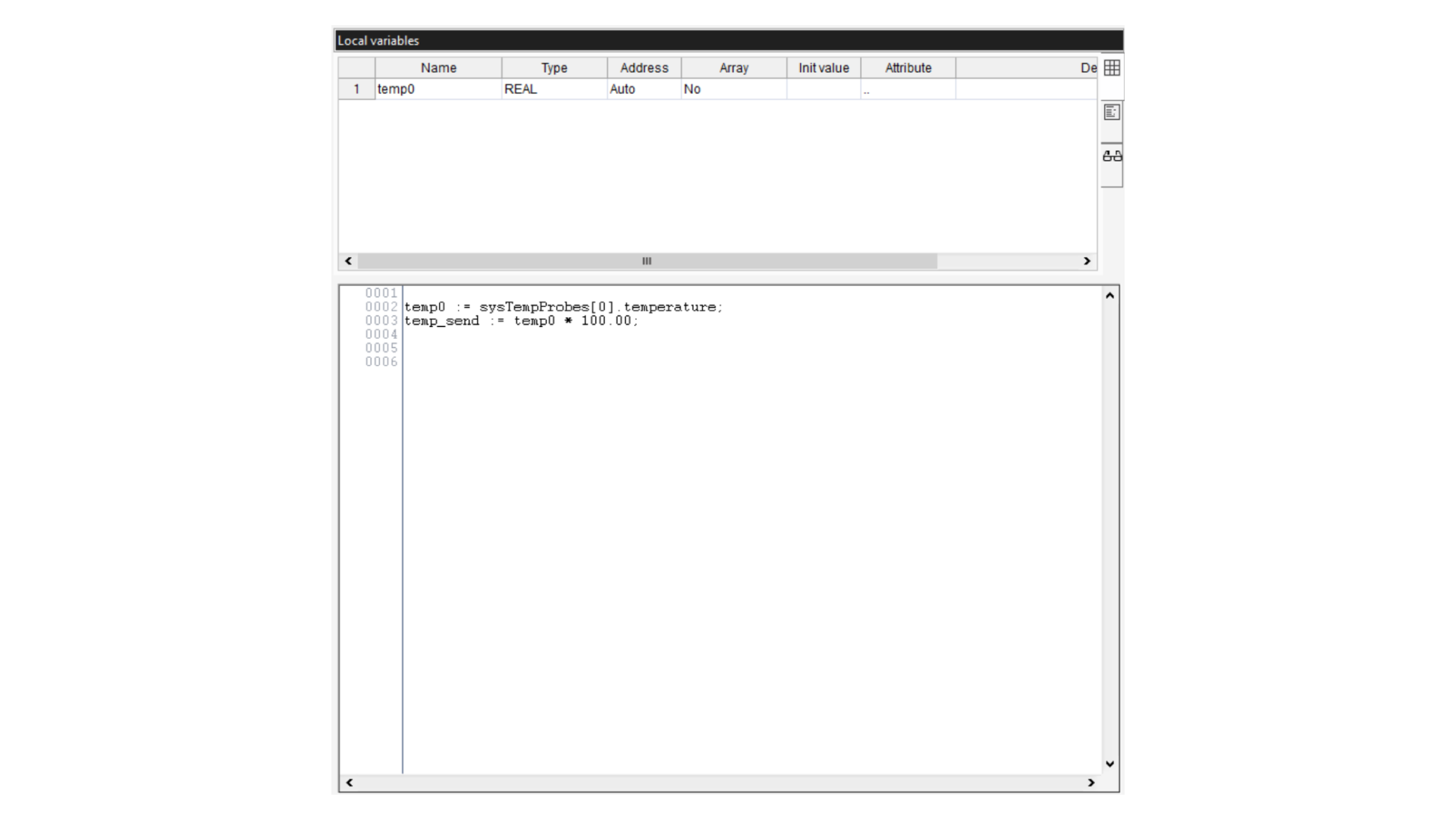
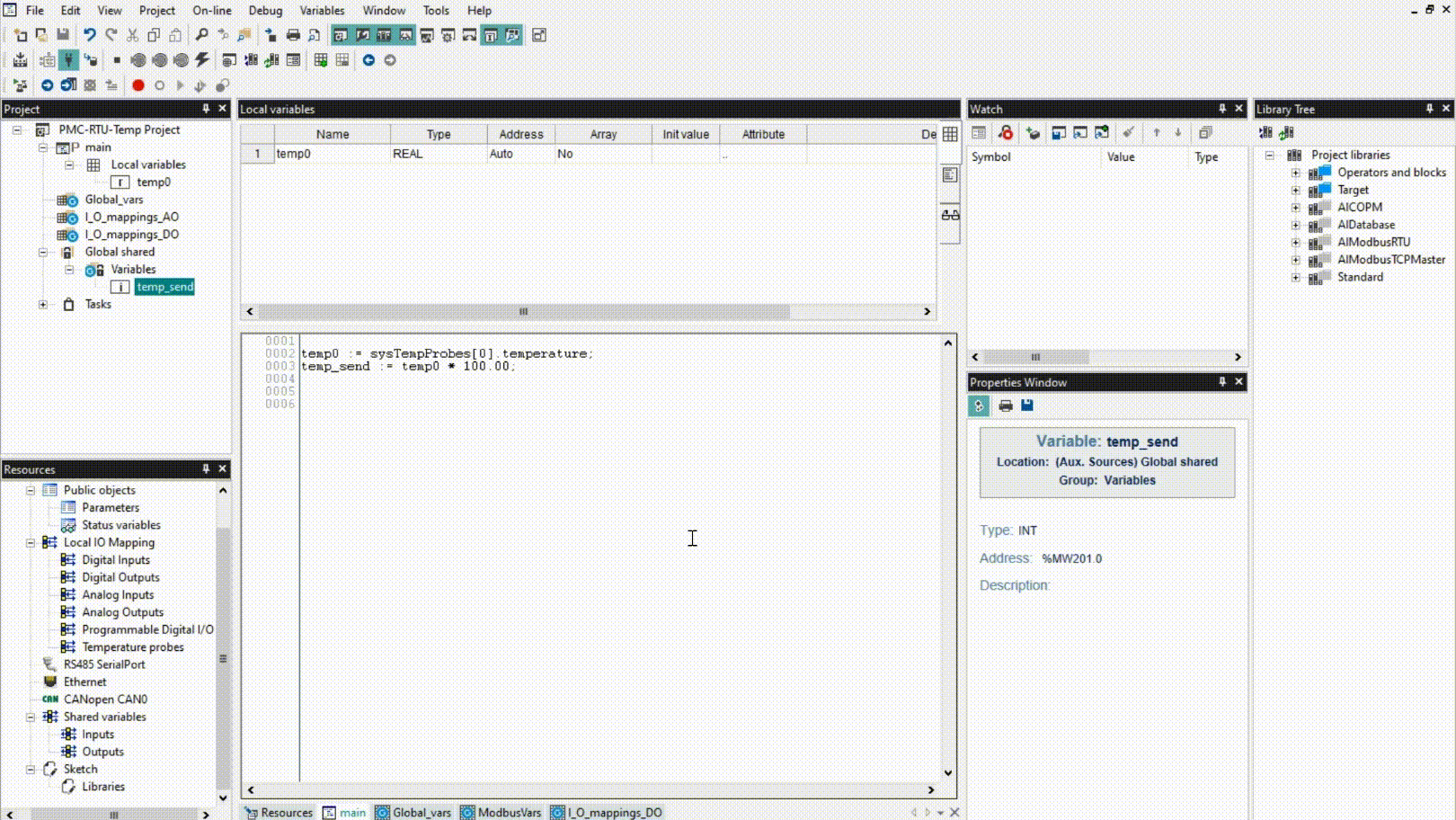
Inside the Project window, double-click on the Main program located under Tasks –> Fast, right-click on the Local variables section on top, and click Insert. You can also do the same by pressing Ctrl + Shift + Ins. Name the variable as temp0 and select the type as Real.
Main Program Code
In the code section, you have to write the following code:
temp0 := sysTempProbes[0].temperature;
temp_send := temp0 * 100.00;
The Main code will read the sensor values from the temperature sensor stored in sysTempProbes[0]. The second line will multiply the temperature value by 1000 to convert it into a convenient integer value to send to Opta™; the Main program should look similar to the following figure:
By default, the project creates an automatic type int global variable called cnt. You can delete it by right-clicking on it and clicking Delete.
Monitor the Values
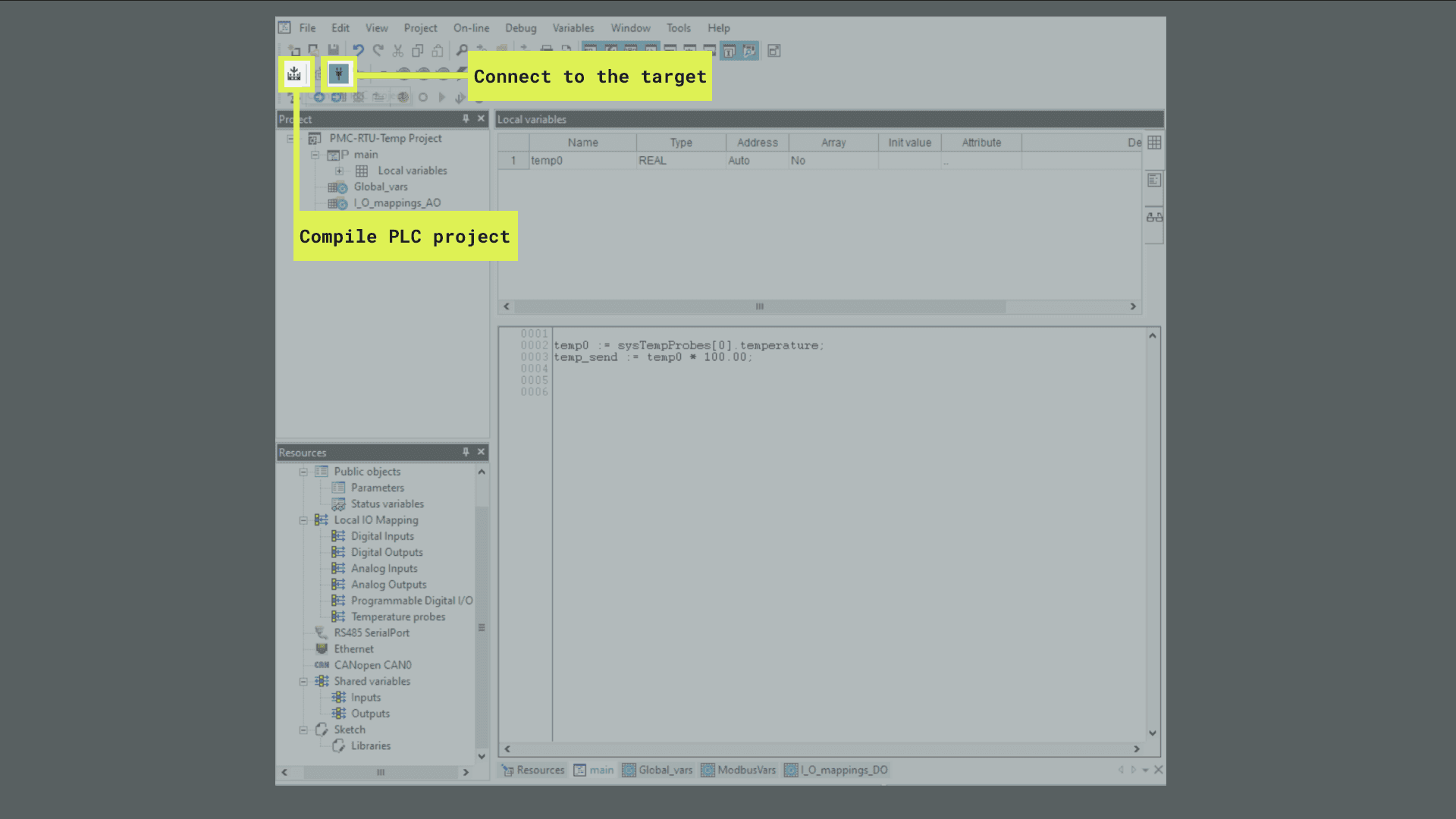
Once followed all the previous steps, you will need to compile the program and download it to the Portenta Machine Control. First, connect your device and click on the Connect to the target button. You can also do the same by following On-line > Connect (We assume that you have activated your board license. If not, please follow this tutorial).
Once connected, click on the Compile PLC Project to compile it. You can also do the same on Project > Compile or by pressing the F7 key:
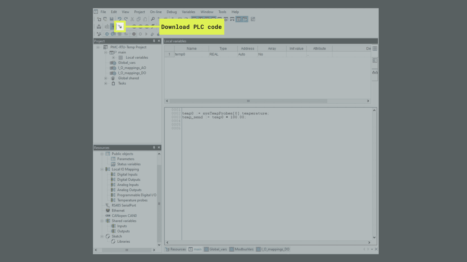
Then click on Download PLC code to download it to the board. You can also do it by going to On-line > Download code or by pressing the F5 key:
To ensure that we are reading correct temperature values on the Portenta Machine Control, you can pick and drop the variable to the Watch window. If you can’t see the Watch window, please try View > Tool window > Watch option.
Opta™ Project
Create the Opta™ Project
After creating and configuring the Portenta Machine Control project, you can create a new project for Opta™ by clicking on File > New Project. It will display a new window where you have to insert a name for the Opta™ project and make sure that the Opta 1.0 is selected on the Target Selection:
Client Modbus Configuration
On the Opta™ side, you will need to configure Modbus as the Client to receive the temperature values. To do that, you need to go to the Resources window and double-click on RS485 SerialPort:
On the Modbus Configuration window, you need to set the following parameters to configure it as the Master (Client):
- Mode: Modbus RTU Master
- Baud rate: 19200 b/s
- Serial Mode: N,8,2 (No parity, 8 data bits, 2 stop bits)
The configuration should contain same setting as the following image:
After configuring the Serial Port, go to the Resources tab and right-click on RS485 SerialPort and click on Add:
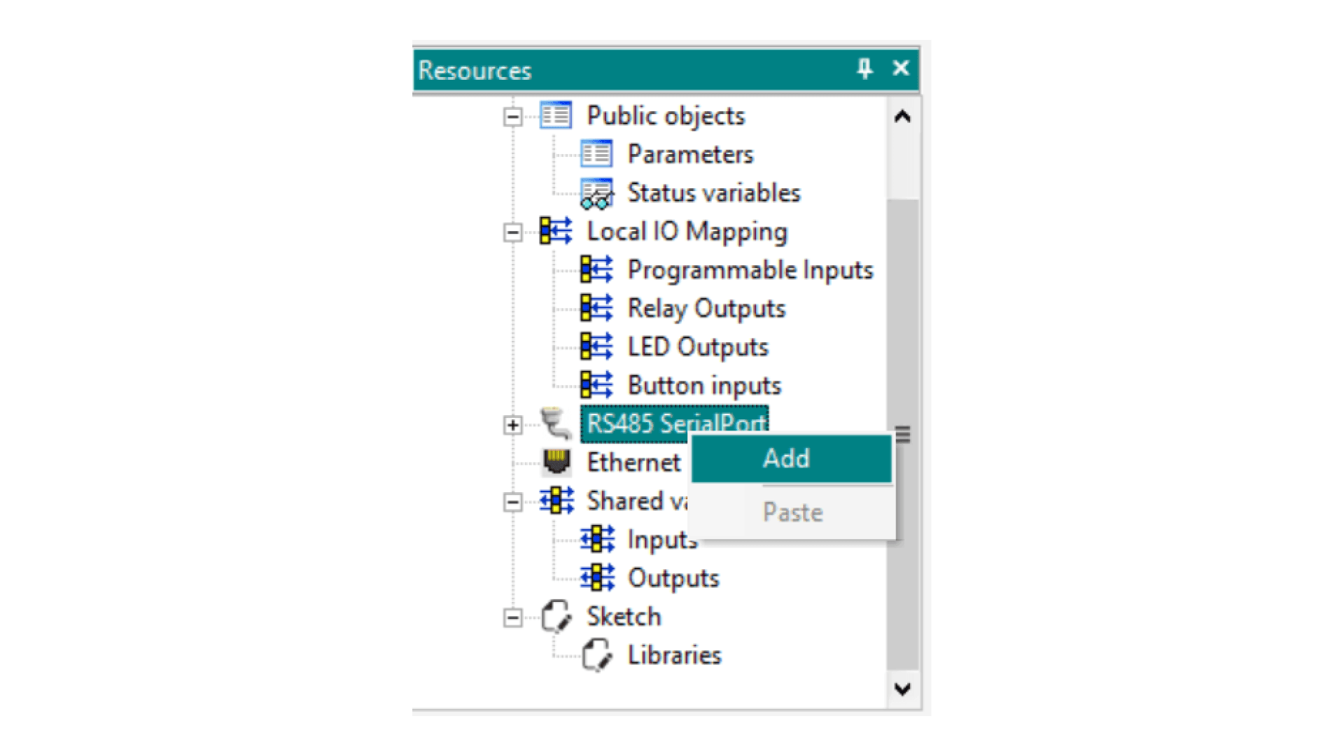
A new window named Device catalog will appear. On this window, select Generic Modbus 1.0 Generic Modbus node and click on Select:
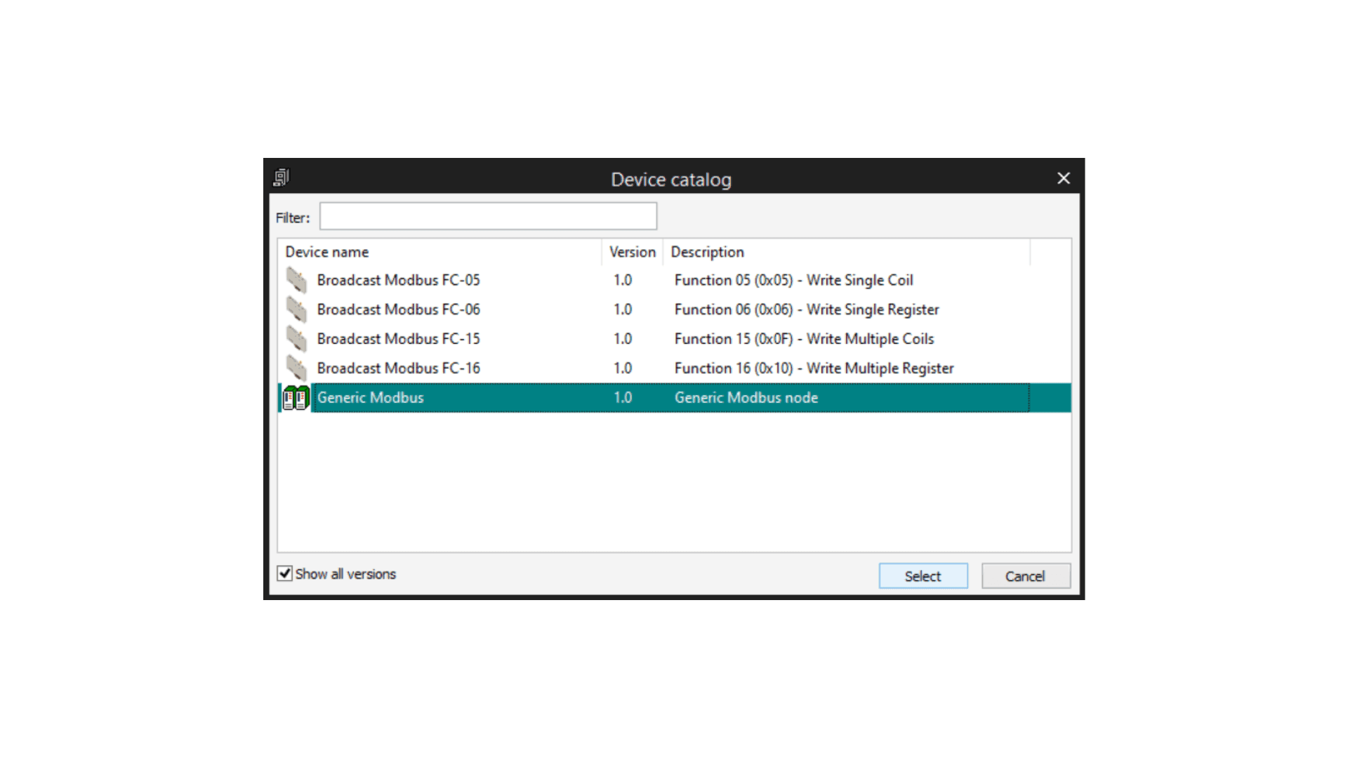
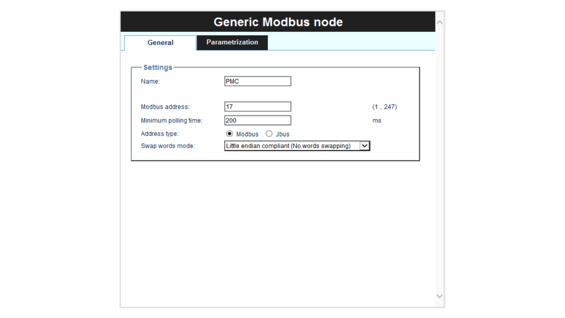
On the Generic Modbus node window, you will set the slave configuration for communicating with the Portenta Machine Control. On Modbus address field, set the server address that we previously configured for the Portenta Machine Control.
It should look as following image:
Now that we added the Portenta Machine Control Modbus node to the net, we need to read the temperature values from its database. To do this, right-click on the PMC node that we have created and click Add:
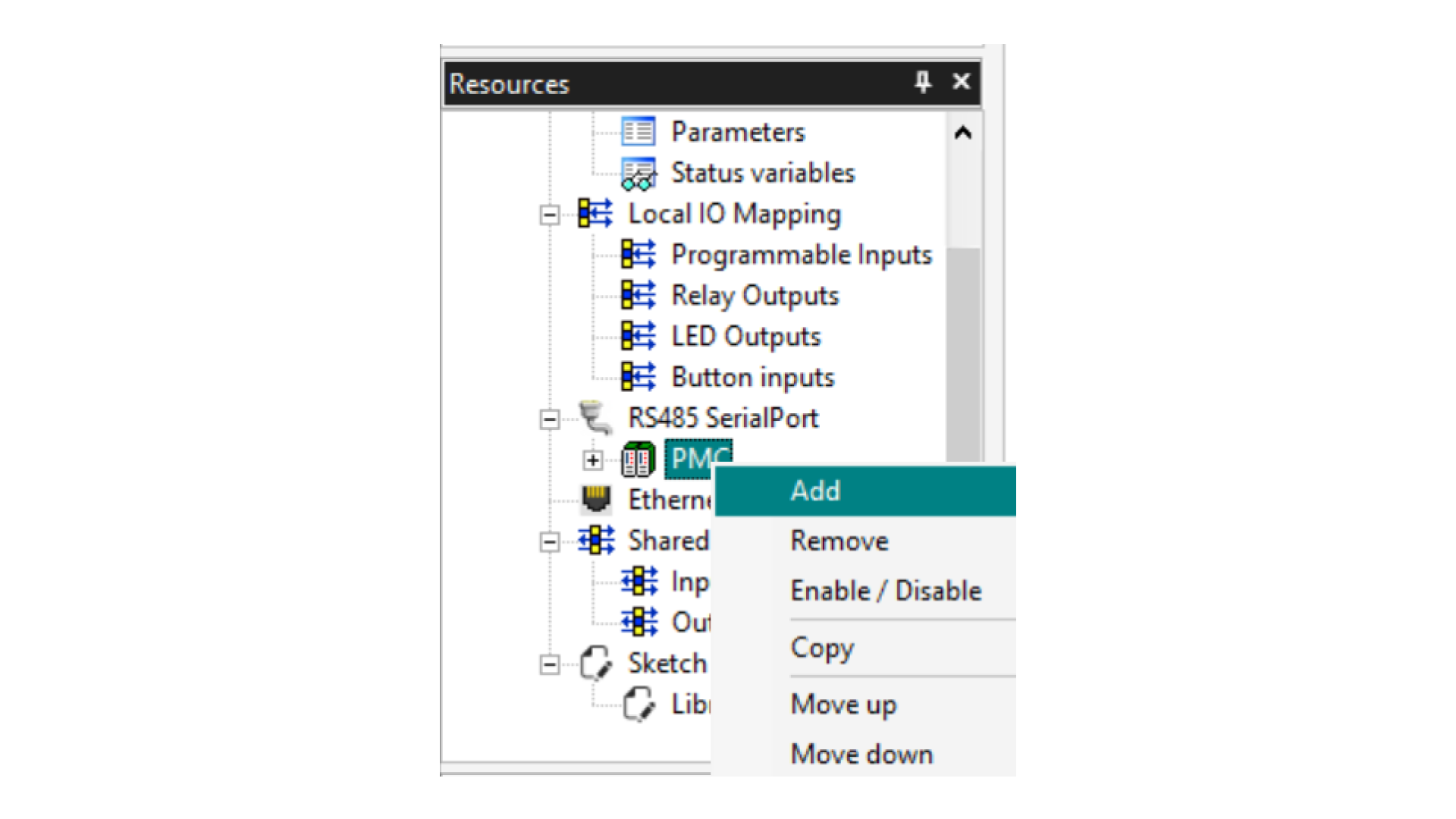
Here is a comprehensive list of the different options that you can add depending on your necessities:
- Modbus FC-01 (Read Coils): reading of one or more RW bits by the slave node
- Modbus FC-02 (Read Discrete Inputs): reading of one or more RO bits by the slave node
- Modbus FC-03 (Read Holding Registers): reading of one or more RW registers by the slave node
- Modbus FC-04 (Read Input Registers): reading of one or more RO registers by the slave node
- Modbus FC-05 (Write Single Coil): writing of a single RW bit on slave node
- Modbus FC-06 (Write Single Register): writing of a single RW register on slave node
- Modbus FC-15 (Write Multiple Coils): writing of one or more RW bits on slave node
- Modbus FC-16 (Write Multiple registers): writing of one or more RW registers on slave node
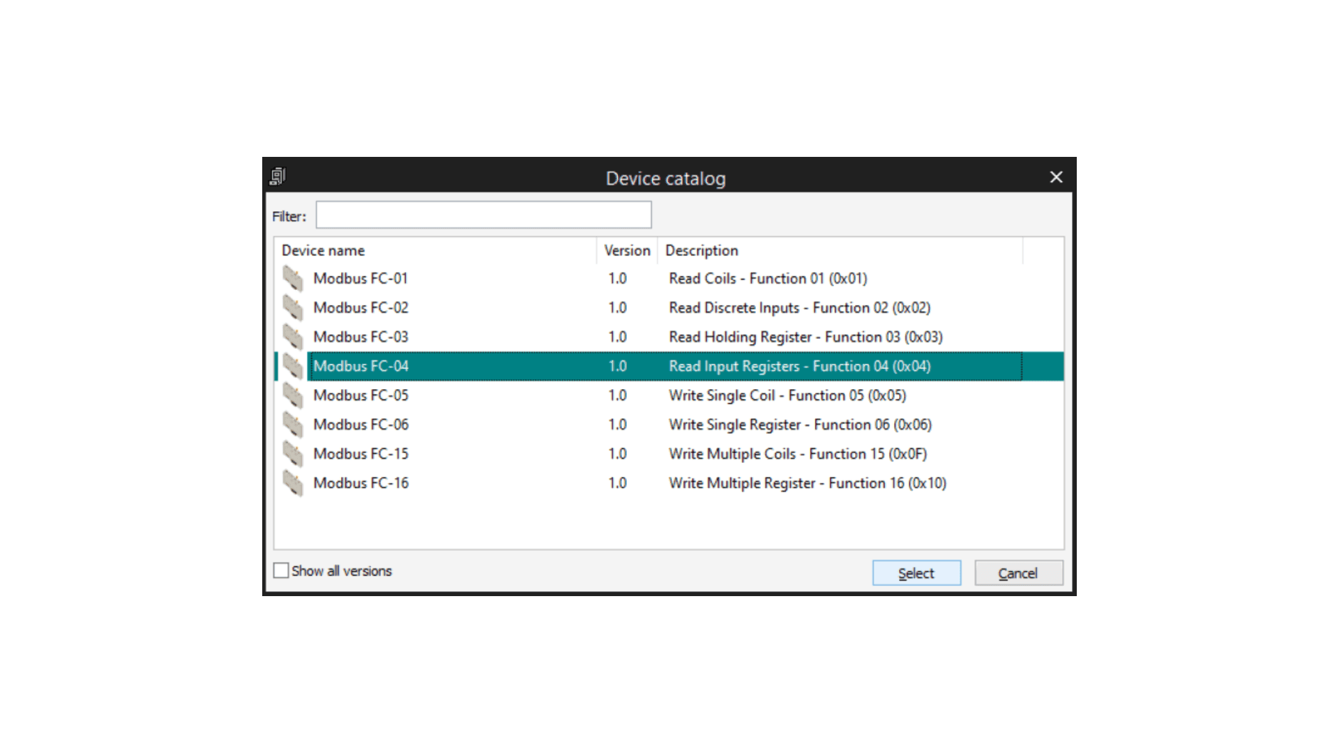
We will select Modbus FC-04 1.0 Read Input Registers - Function 04 (0x04) to read the temperature values on the Portenta Machine Control database, and click Select.
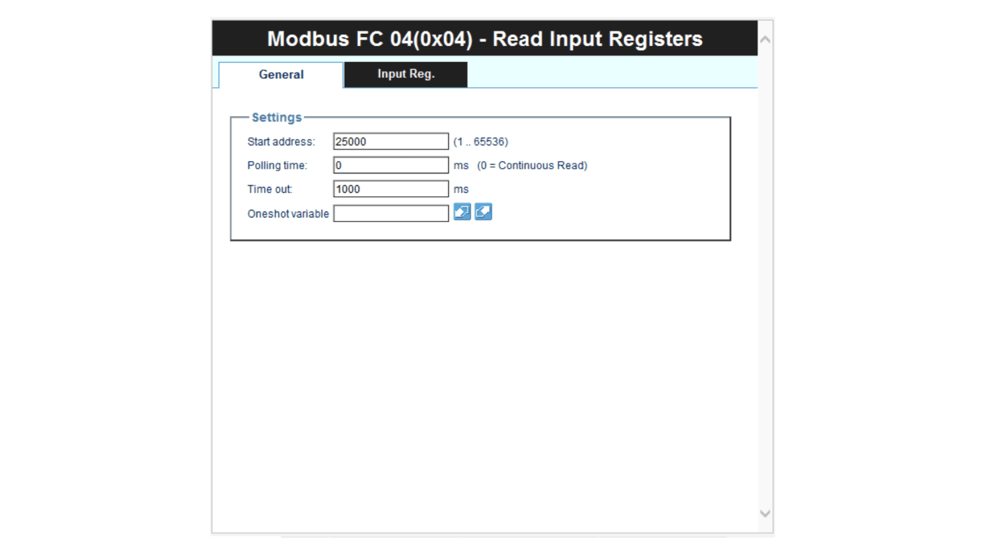
After clicking on Select, a new configuration window will appear. Here we will configure the Reading of Input Registers. To do this, set the start address of the memory address that we set before on the Portenta Machine Control configuration, as shown in the following image:
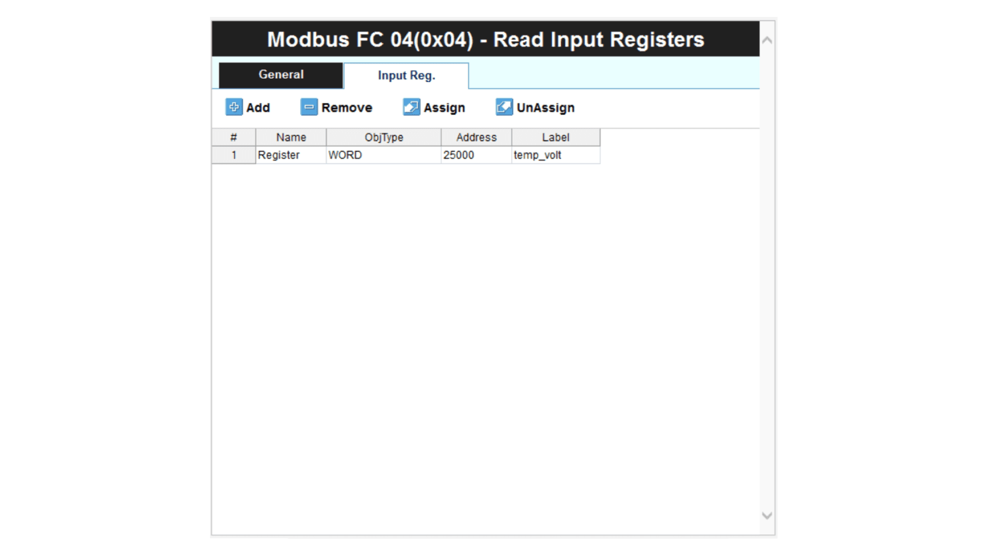
With the parameters defined, click on the Input Reg. tab inside the same configuration window. Inside this window click add on the left corner, and type temp_volt or a name of your choice. This will be the variable where we store the reading values for the Portenta Machine Control database. That tab should look like this:
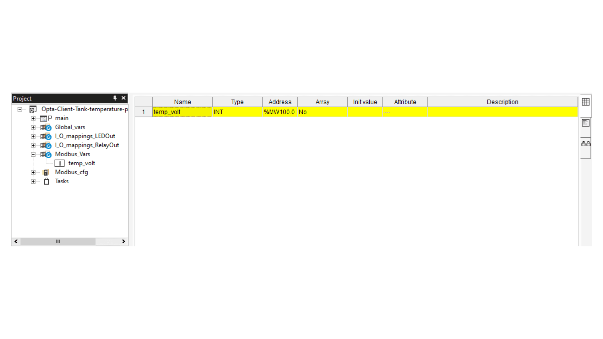
To select a type for this variable, we need to go to the Projects window and double-click on Modbus_Vars, and then double-click on temp_volt. Write INT in the Type column to assign an Integer type to the variable. In the future, we will convert this value into comprehensive data. The variable window should be like this:
Main Program Code
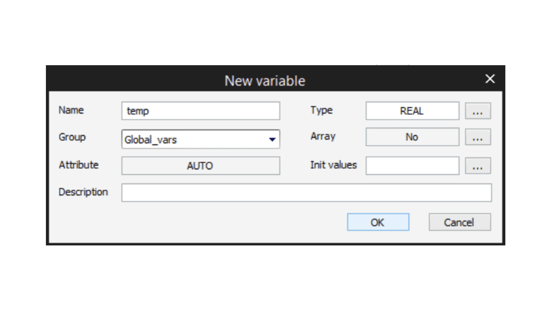
Before going with the main program code, go to the Project window, right-click on Global_vars > New variable > Automatic and set temp as the variable name, and type REAL on the variable type and click Ok:
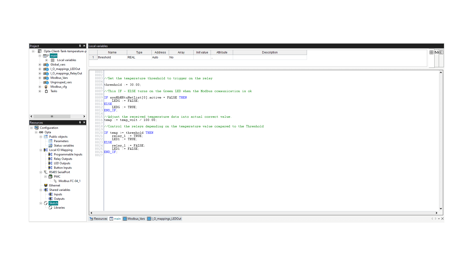
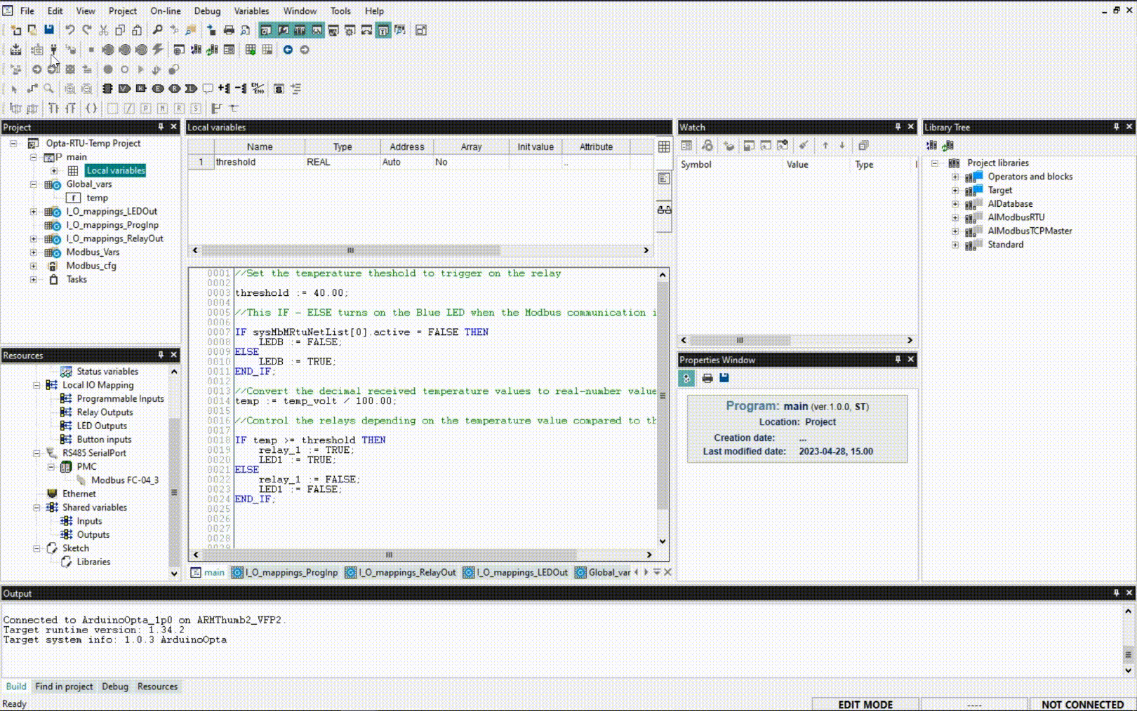
Now that we have created the global variable where we are going to store the temperature values in REAL type format, go to main by double-clicking on it in the Project window. In the Local variables tab, right-click on a white space and click Insert. You can also do the same by pressing Ctrl + Shift + Ins. For this new variable, set the name threshold and Type as REAL.
In the code window, paste the next code:
//Set the temperature threshold to trigger on the relay

threshold := 30.00;

//This IF - ELSE turns on the Green LED when the Modbus communication is ok

IF sysMbMRtuNetList[0].active = FALSE THEN
    LEDG := FALSE;
ELSE
    LEDG := TRUE;
END_IF;

//Adjust the received temperature data into actual correct value.
temp := temp_volt / 100.00;

//Control the relays depending on the temperature value compared to the Threshold

IF temp >= threshold THEN
    relay_1 := TRUE;
    LED1 := TRUE;
ELSE
    relay_1 := FALSE;
    LED1 := FALSE;
END_IF;
The main program window should look like this:
The variables LED1, LEDG, and relay_1 represents onboard features of Opta™.
LED1: is the number one status LED.LEDG: represents the Green LED.relay_1: represents the relay terminal one.
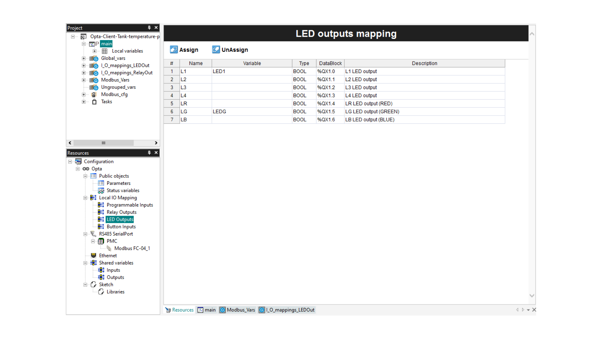
To use the variables LED1, LEDG, and relay_1 in the main program, they need to be linked to their corresponding hardware outputs. To achieve this:
- Navigate to the Resources tab.
- Proceed to LED Outputs.
- Associate the
LED1andLEDGvariables with their respective hardware outputs: ‘L1’ and ‘LG’.
The setup should resemble the following image:
Following a similar process:
- For the
relay_1variable, associate it with theO1hardware output. - This can be done in the ‘Relay Outputs’ mapping section:
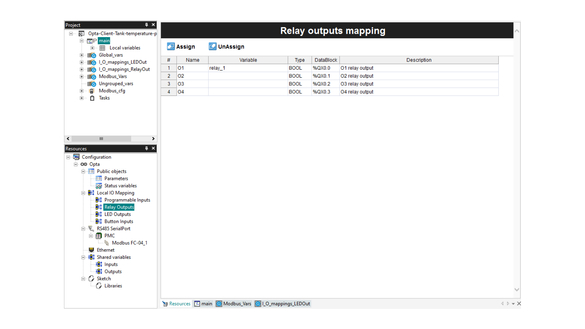
Mapping onboard elements ensures that your software instructions directly influence the corresponding physical hardware components, bridging your program’s logic with real-world actions.
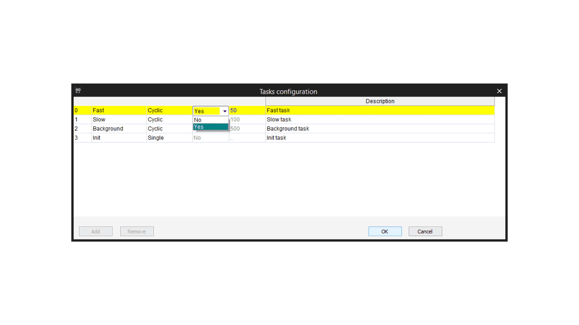
Task Configuration
It is recommendable to set an executing period of 50 ms for the main task; to do this, double-click on Tasks inside the Project window; a new Tasks Configuration window will appear.
On this window, change the Set period option of the Fast Task to Yes and set choose 50 ms period. If you want to learn more about task configuration, take a look at this tutorial.
Monitor the Values
Before begin monitoring the values, connect your Opta™, compile the code, and download it to the board as shown in the Portenta Machine Control Monitor the Values section. The following short clip provides an overview of what you can expect during the operation:
Note: temp_volt variable refers to the read values from the Portenta Machine Control Database through Modbus RTU protocol.
If you reach the threshold of 30 degrees Celsius, the Opta™ device’s relay will close and the LED1 will turn on. Remember that you can set this value to any value you need by changing the threshold parameter in the main program code.
Download the PLC Project
We recommend you follow all the steps to understand thoroughly how the project works and what are we doing in each step, but you can also directly download the Arduino PLC IDE Projects on the Software Requirements section and uncompress the Zip file on your Arduino PLC IDE Projects Folder to set and test the example project.
Conclusion
In this tutorial, you have learned how to measure and control the temperature of an industrial tank by reading the temperature values using an RTD with the Portenta Machine Control and sending it via Modbus RTU on the RS-485 interface to process the reading values and controlling a relay, activating a cooling system when a temperature has reached the threshold.
Next Steps
It has been a theoretical guide on how to do it, so the challenge in this project now is to apply it in a real environment scenario, taking into account some other factors and applying PID, normally used in these industrial applications.
Note that this same circuit can be used for many more scenarios than the temperature control of an industrial tank, as well the heating control of a home, or the refrigeration of a food chamber.