How to Use an HMI with Finder OPTA via Modbus TCP
Guide and Tutorial | How to Use an HMI with Finder OPTA via Modbus TCP
How to Use an HMI with Finder OPTA via Modbus TCP
Learn how to configure Finder OPTA as a Modbus TCP server in CODESYS, exposing a variable through a Modbus register so an external HMI can read and display it.
Overview
Thanks to its integrated Ethernet port, Finder OPTA can act as a Modbus TCP server and expose the values of its internal variables as Modbus registers to any connected Modbus TCP client. This feature is especially useful when you want to display these values on HMIs that support Modbus TCP, allowing - for example - to integrate Finder OPTA into a monitoring system.
In this tutorial, we will see how to configure the Finder OPTA as a Modbus TCP server using CODESYS. To make the example concrete, we will implement a simple program that contains a counter from 0 to 100, which is incremented with each PLC execution cycle. The counter value will then be published by the Modbus TCP server as an Input Register, making it readable by any Modbus TCP client.
We will start by creating a new project in CODESYS and writing the ST program that implements the counter. Next, we will configure the Ethernet port of Finder OPTA, and finally we will add and configure the Modbus TCP server, mapping the counter variable to one of the Input Registers.
Once the configuration is complete, we will download the project to the Finder OPTA and show two examples of HMI programs that read and display the value contained in the Input Register of the Modbus TCP server. For this tutorial, we verified the system using a Kinco GR070E HMI and a Weintek MT8051iE HMI.
Goals
- Configure Finder OPTA Ethernet port in CODESYS
- Configure a Modbus TCP server on Finder OPTA in CODESYS
- Expose the content of a variable to a Modbus TCP client
- Verify the operation of the Modbus TCP server with a Kinco GR070E HMI or a Weintek MT8051iE HMI
Requirements
Before starting, make sure you have:
- Finder OPTA CODESYS PLC (x1)
- 12W or 25W switching power supply for OPTA (1x)
- Ethernet cable (x1)
- Kinco GR070E HMI or Weintek MT8051iE HMI with its power supply (x1)
- CODESYS development environment installed with the OPTA Configurator plug-in. You can find an installation guide at this link.
- Properly configured network: your PC must be able to communicate with Finder OPTA via Ethernet. Configuration guide available here.
To follow this tutorial, you will need to power the Finder OPTA with the switching power supply for OPTA CODESYS. You will also need to power the HMI panel with an appropriate power supply: please refer to the documentation for your specific HMI model.
Instructions to create the Modbus TCP server
This tutorial shows how to configure Finder OPTA as a Modbus TCP server to makethe value of a variable available via Modbus TCP. In this way, an HMI that supports the Modbus TCP protocol can read and display the value.
Creating a CODESYS Project
Open CODESYS.
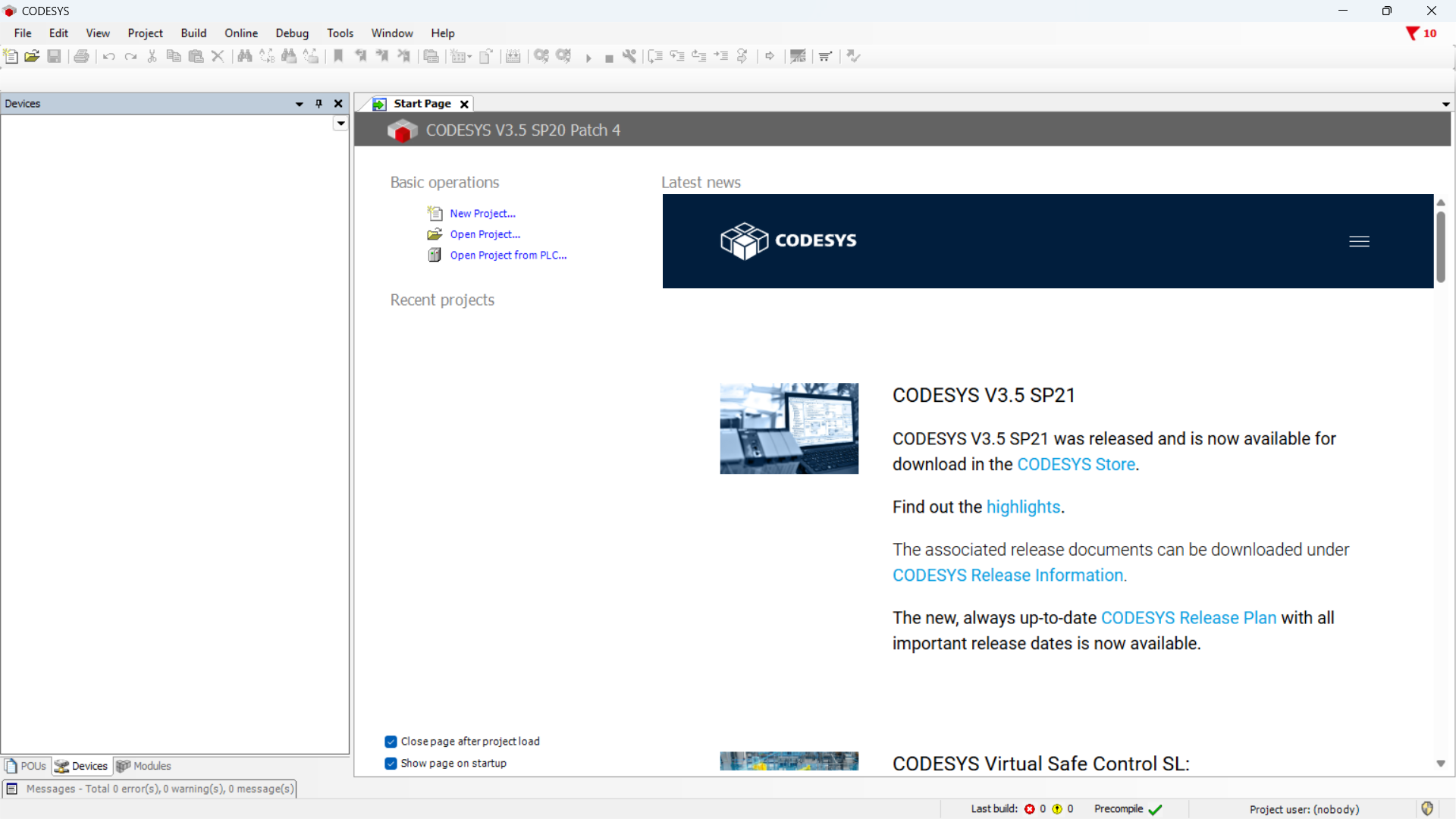
Create a new project and choose Standard project.
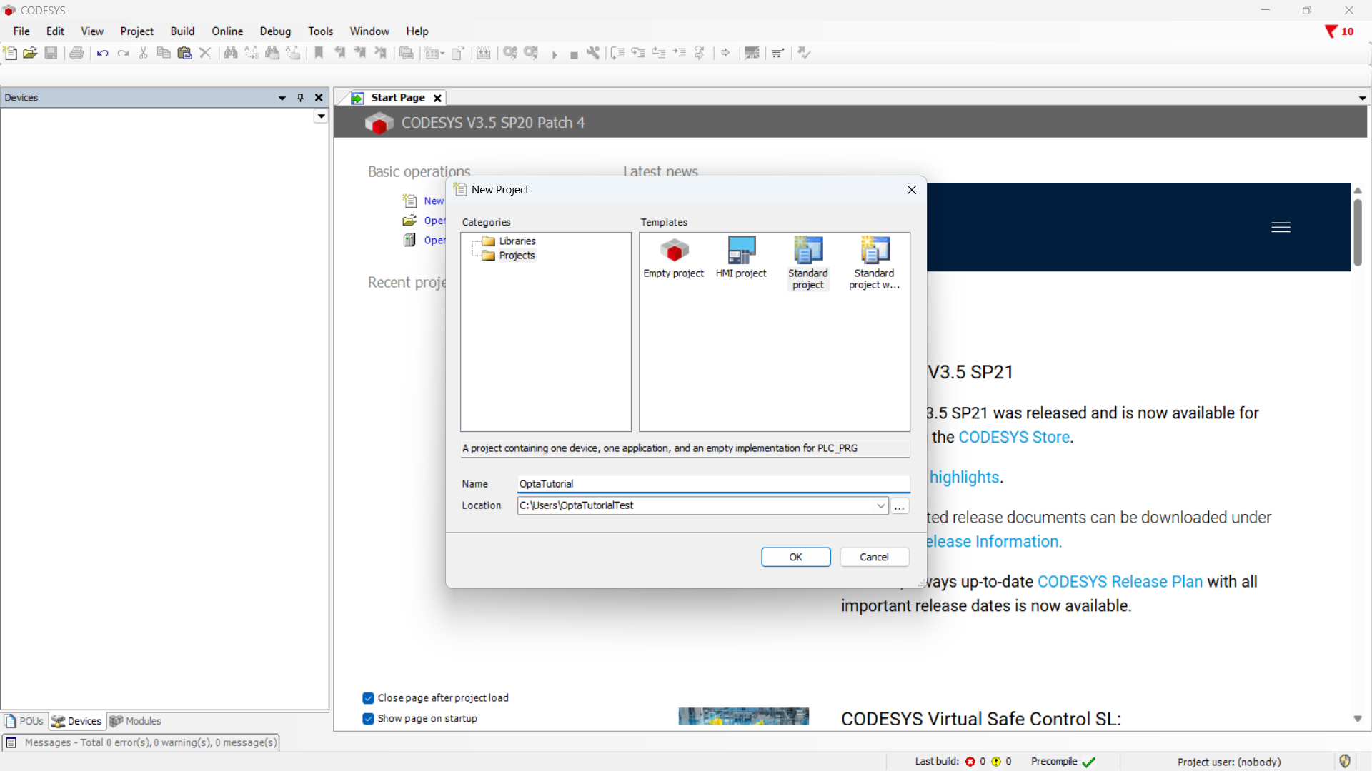
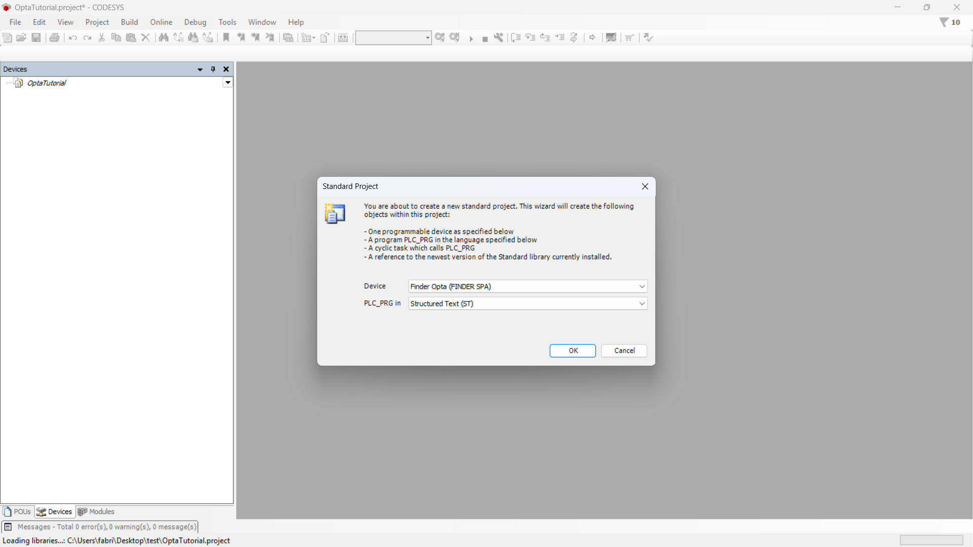
Make sure the device is Finder Opta, then select the program language.
Identifying Finder OPTA via Ethernet
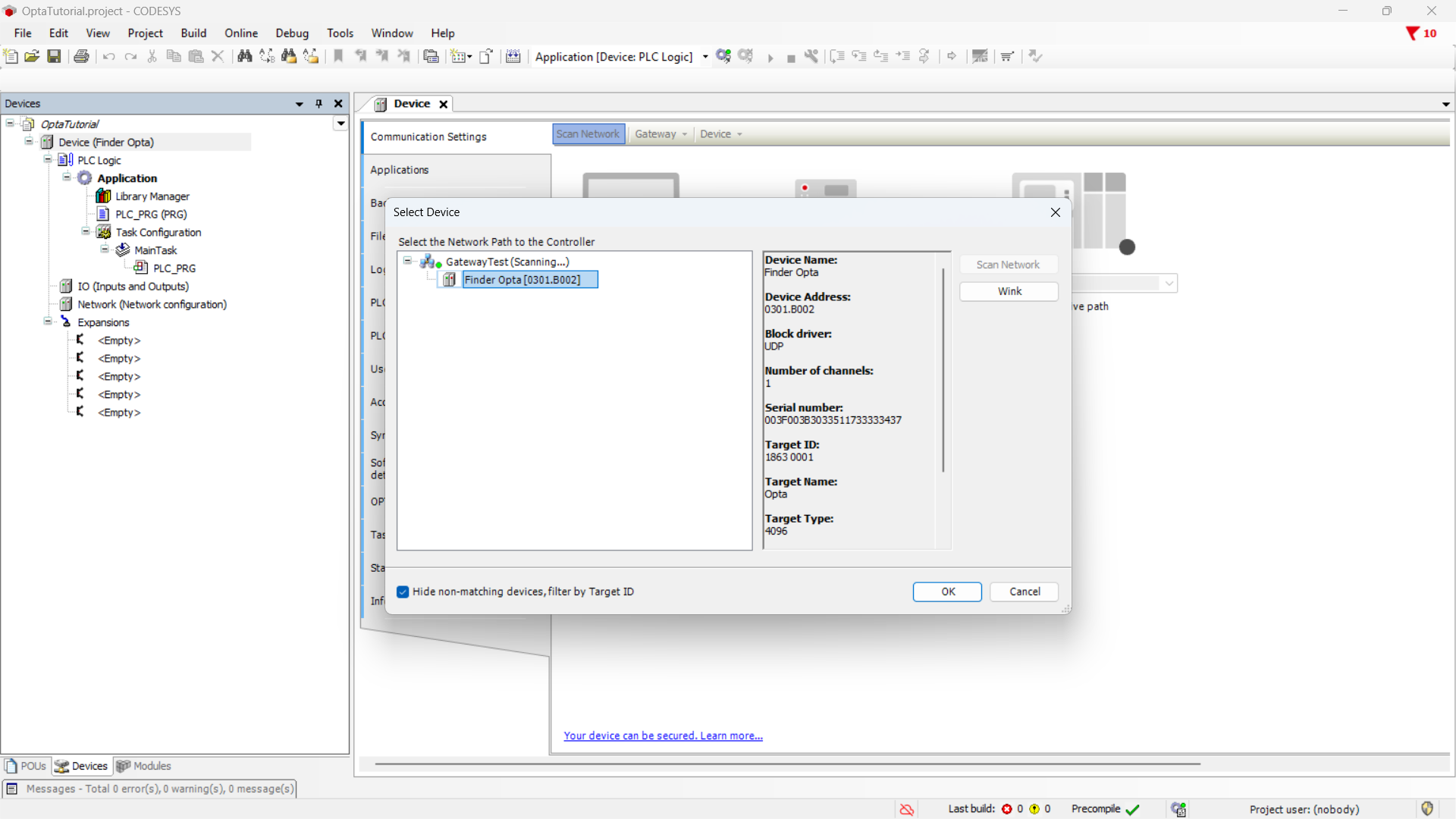
Double-click the Device (Finder Opta) entry in the Devices menu. A tab will open as shown below.
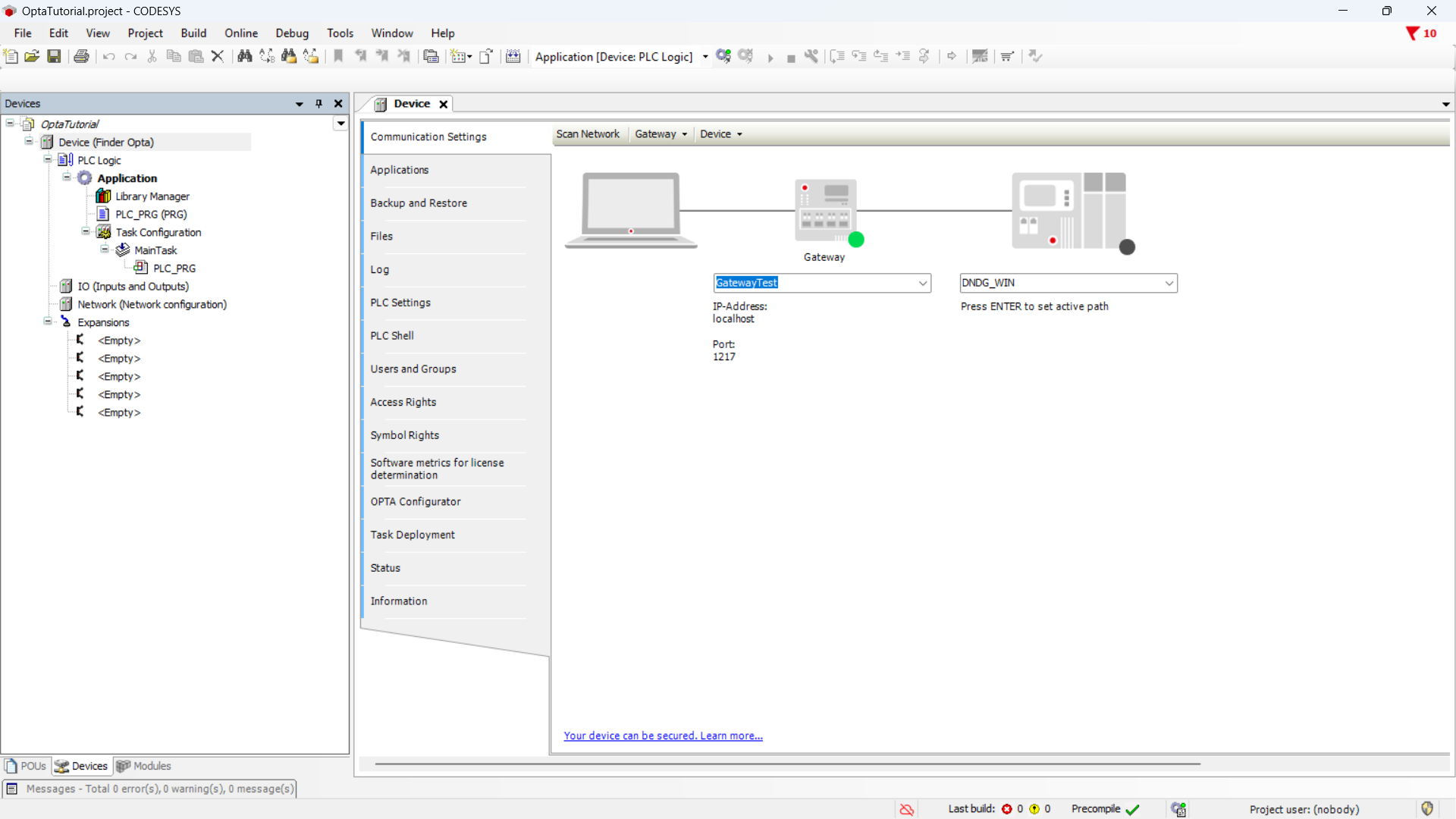
Click the Scan network button and make sure you see the Finder OPTA device appear under the Gateway, then press OK.
Preparing the ST program
Now write the ST program that implements the counter from 0 to 100. At the end of each cycle, the counter value is copied into a variable that we will map to the Input Register of the Modbus TCP server.
In the side menu, click on PLC_PRG (PRG).
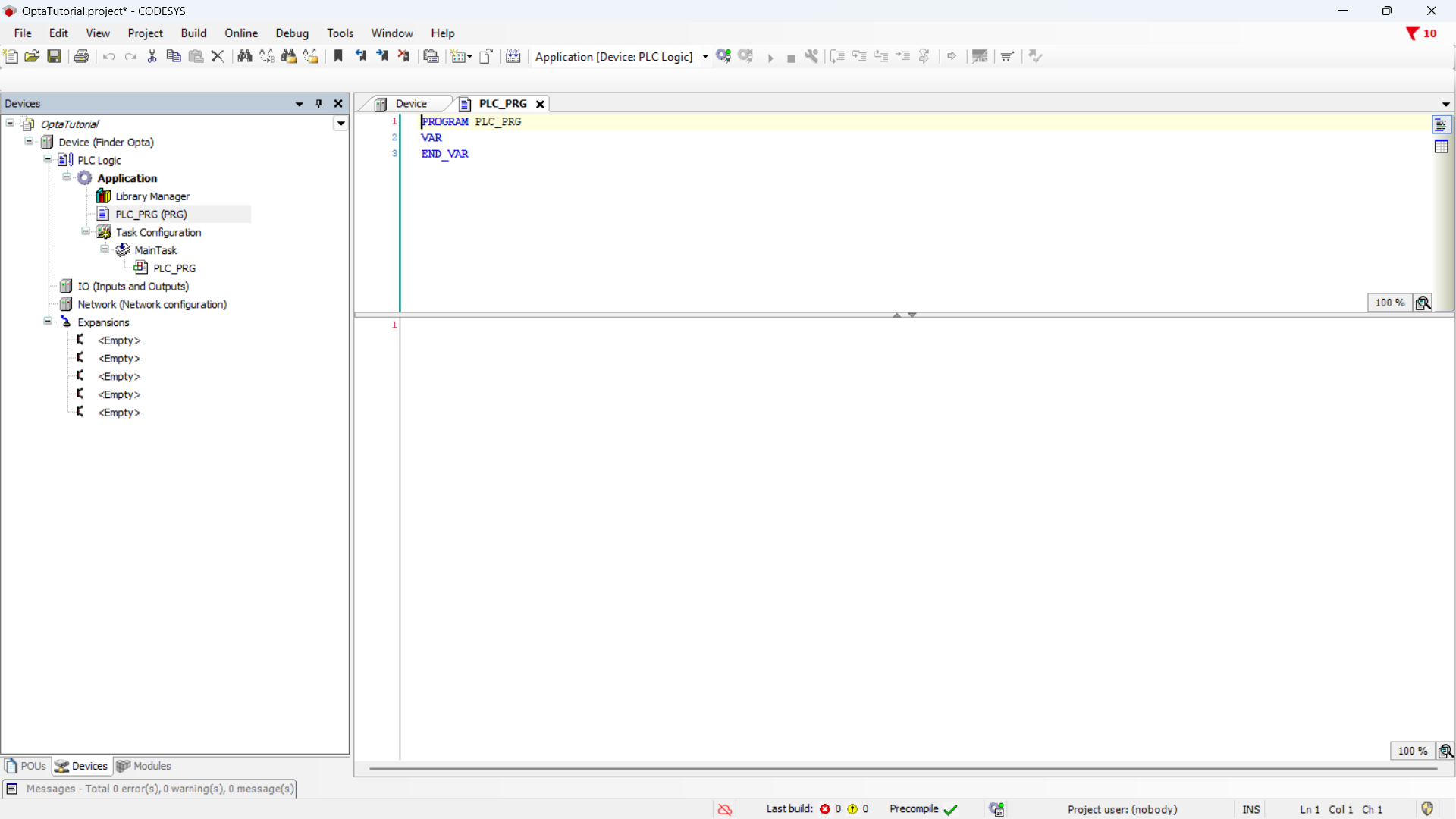
In the upper part of the editor - dedicated to variable definitions - enter the following code:
PROGRAM PLC_PRG
VAR
    count: WORD := 0;
    mbCount: WORD;
END_VAR
In the lower part of the editor - dedicated to the program logic - enter the following code:
IF count < 100 THEN
    count := (count + 1);
ELSE
    count := 0;
END_IF

mbCount := count;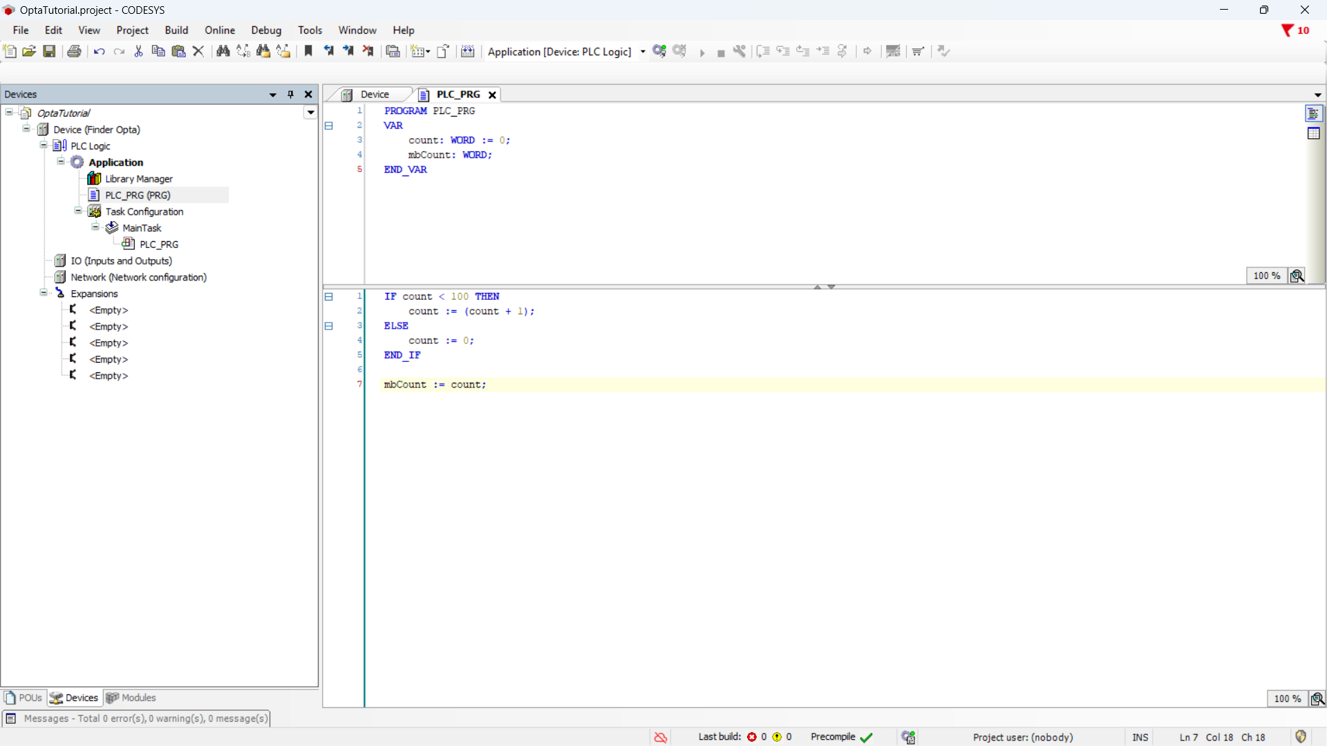
Ethernet port configuration
In this section, we will configure the Ethernet port of the Finder OPTA in CODESYS, specifying the IP address at which the Modbus TCP server will be accessible.
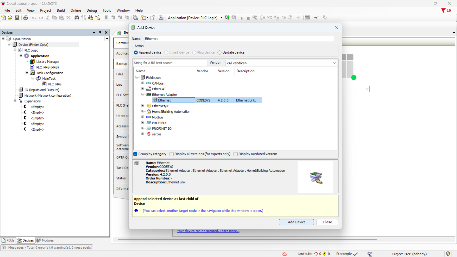
Let's start by adding the Ethernet adapter: right-click on the
Device (Finder OPTA) item and choose Add Device....
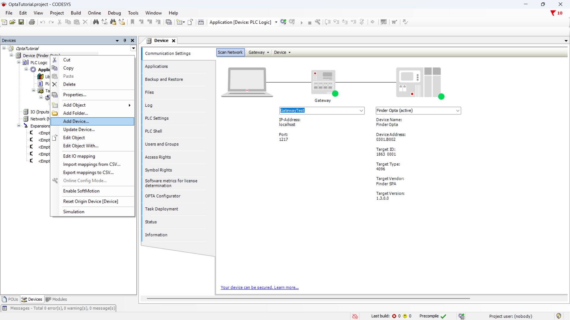
From the menu, expand the Ethernet Adapter item, select Ethernet, and click
Add Device.
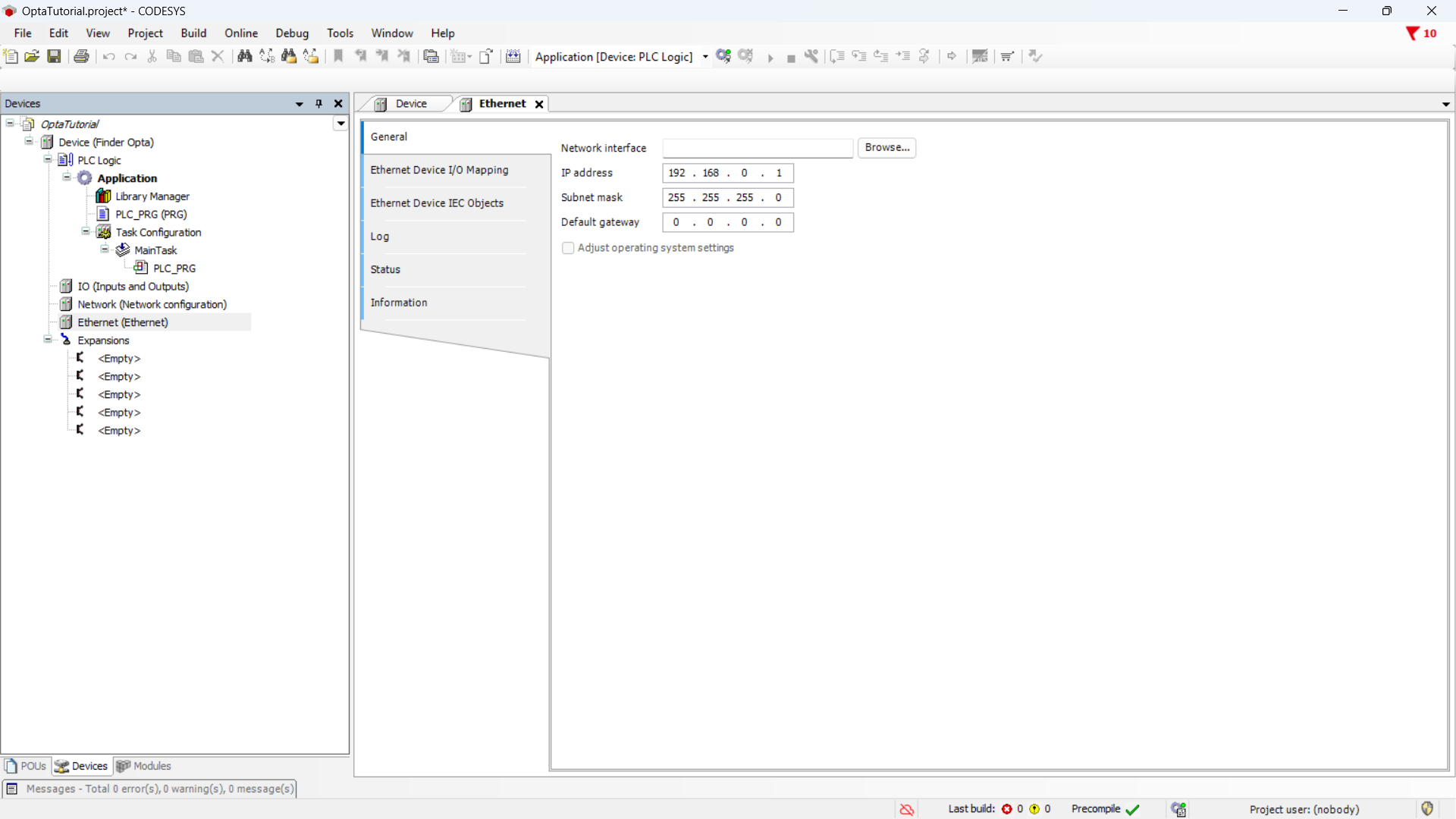
Now, double-click on the Ethernet (Ethernet) item in the side menu.
At this point, read the network configuration from the Finder OPTA: clicking
the Browse... button will open a window with the network parameters of the
connected device.
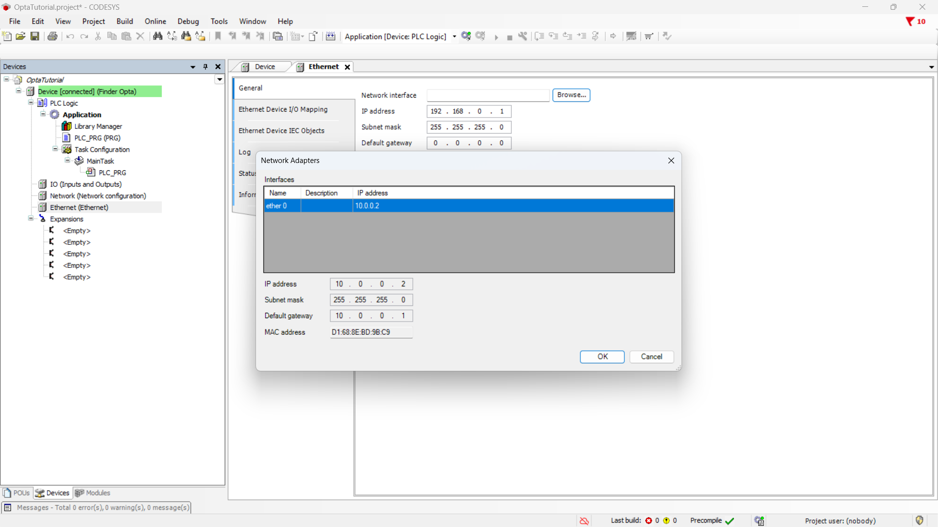
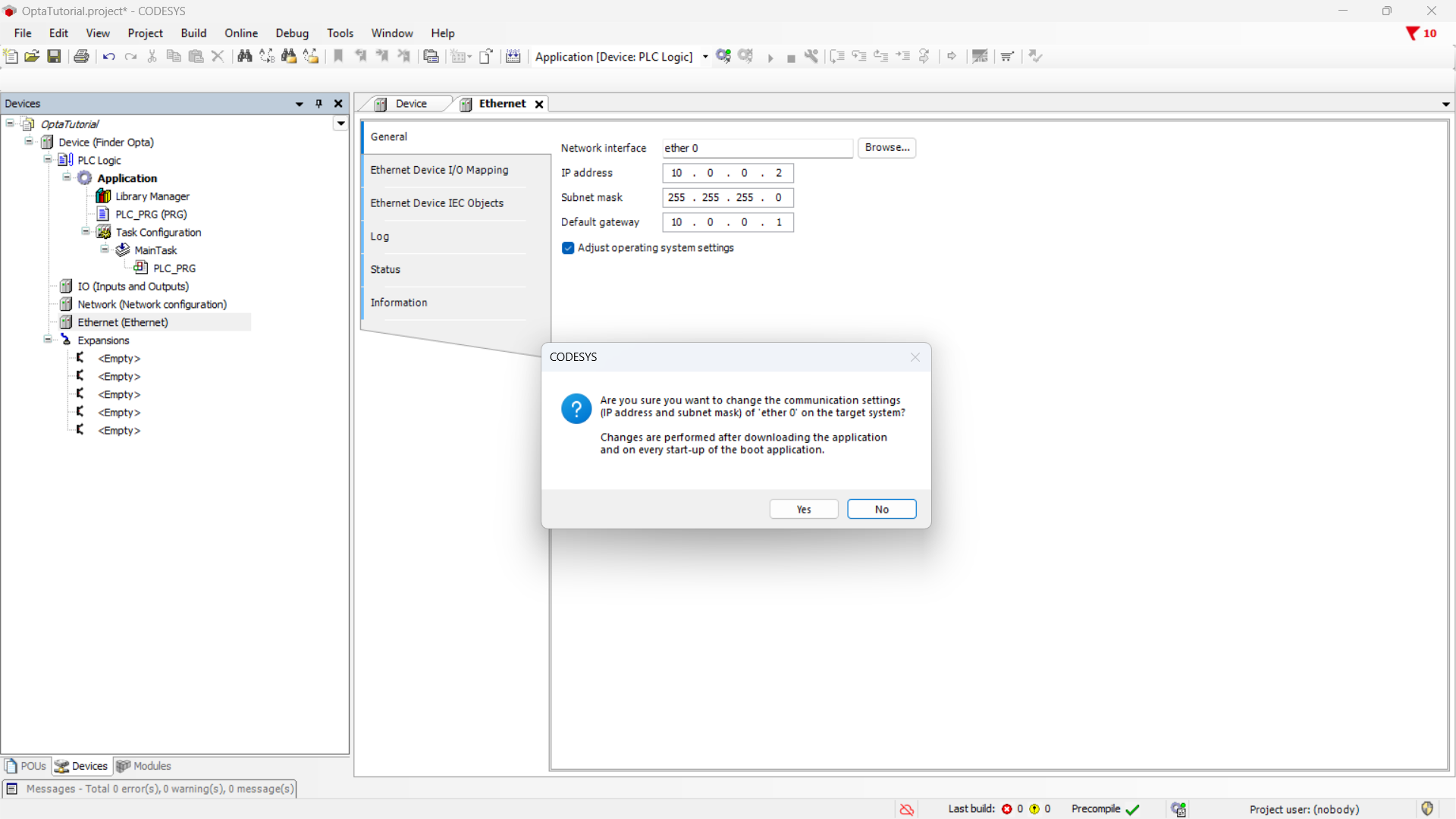
Press OK to keep the Finder OPTA network parameters. Before continuing,
remember to check the Adapt operating system settings option and then click
Yes to confirm the change.
Modbus TCP Server configuration
In this section, we will configure a Modbus TCP server on the Finder OPTA. This server can be reached via Ethernet at the previously configured IP address. The Modbus TCP server exposes the value of the counter calculated by the ST program in an Input Register.
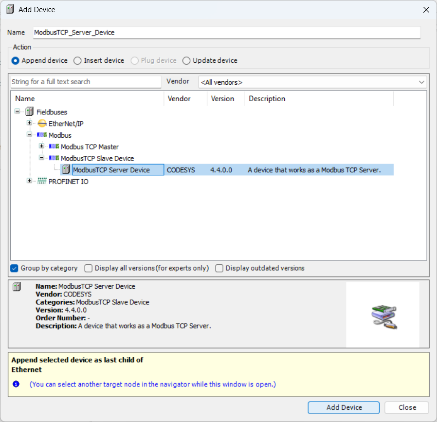
First, add a Modbus TCP slave device to the Finder OPTA Ethernet port:
right-click on the Ethernet item and select Add Device.... Next, we will
configure a Modbus TCP server on the slave. From the menu, expand the Modbus
item, then ModbusTCP Slave Device, click on ModbusTCP Server Device and
Add Device.
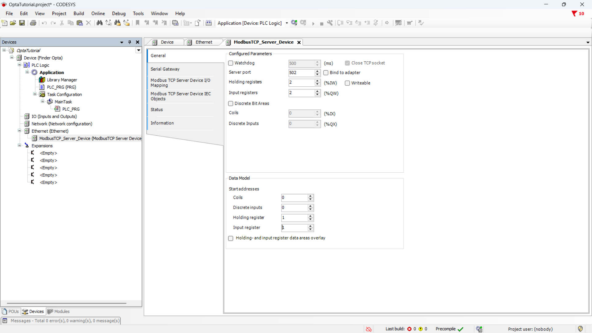
Now you can configure the registers of the Modbus server. Specifically, you need at least one Input Register to hold the counter value. Set the values as follows:
- Server port:
502, the default port for the Modbus TCP protocol. - Holding registers:
2, we are not using them so we set them to the minimum value. - Input registers:
2, we will use a single Input Register but the minimum value is 2. - Holding register:
1, the starting address for the Holding Registers. - Input register:
1, the starting address for the Input Registers.
All other parameters can be left at their default values.
The CODESYS configurator counts addresses starting from 0 and allows
configuring the Modbus TCP server registers starting from address 0.
However, the IDEs used to program some HMIs accept 1 as the minimum value: to
make this tutorial compatible with as many HMIs as possible, the starting
addresses of our Modbus TCP server are set to 1. Furthermore, in the Modbus
protocol, Holding Registers and Input Registers belong to distinct address
spaces, so there is nothing to prevent them from both starting at the same
address.
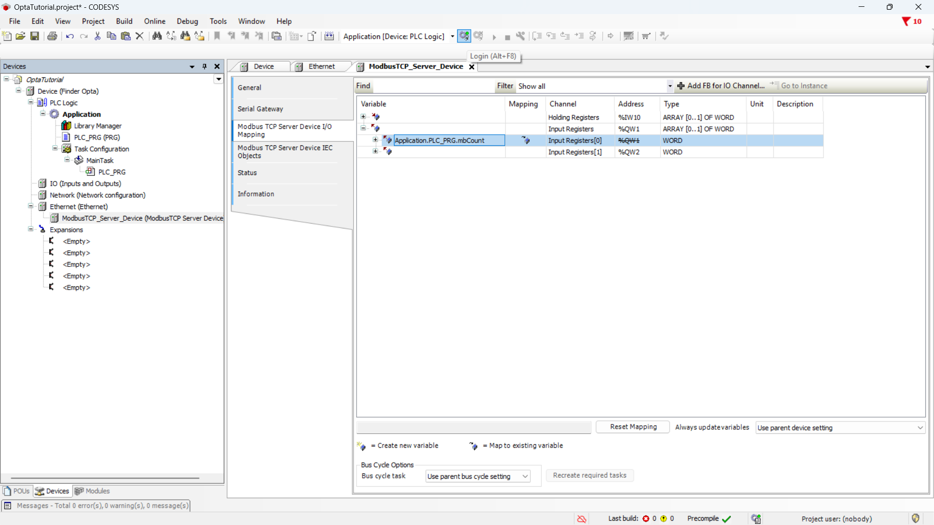
Now you need to associate the counter variable with the Input Register of the
Modbus TCP server. Click on the Modbus TCP Server Device I/O Mapping section,
and in the table expand the Input registers section, then double-click
on the Variable cell to make the options button appear.
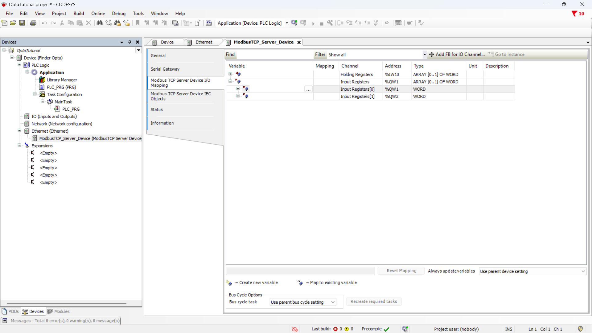
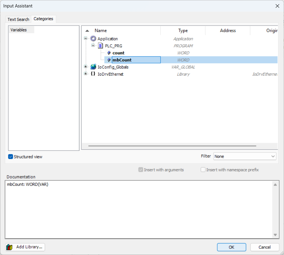
Click the options button to bring up the list of variables, expand the
Application item and the PLC_PRG item. At this point, click on the
mbCount variable and press OK to assign it to the Input Register.
The summary shows the variable assigned to the Input Register.

After this step the counter value is replicated within the Input Register of the Modbus TCP server. A client will then be able to access the register to read and display the value.
Downloading the program to Finder OPTA
In this step, we will download the program and hardware configuration to the Finder OPTA, so it can run the code we just wrote and return the counter value.
Download the program and the configuration to the device by pressing the green
button at the top labeled Login.
Once the download is complete, the program is loaded onto the Finder OPTA. Run
it by pressing the Start button.
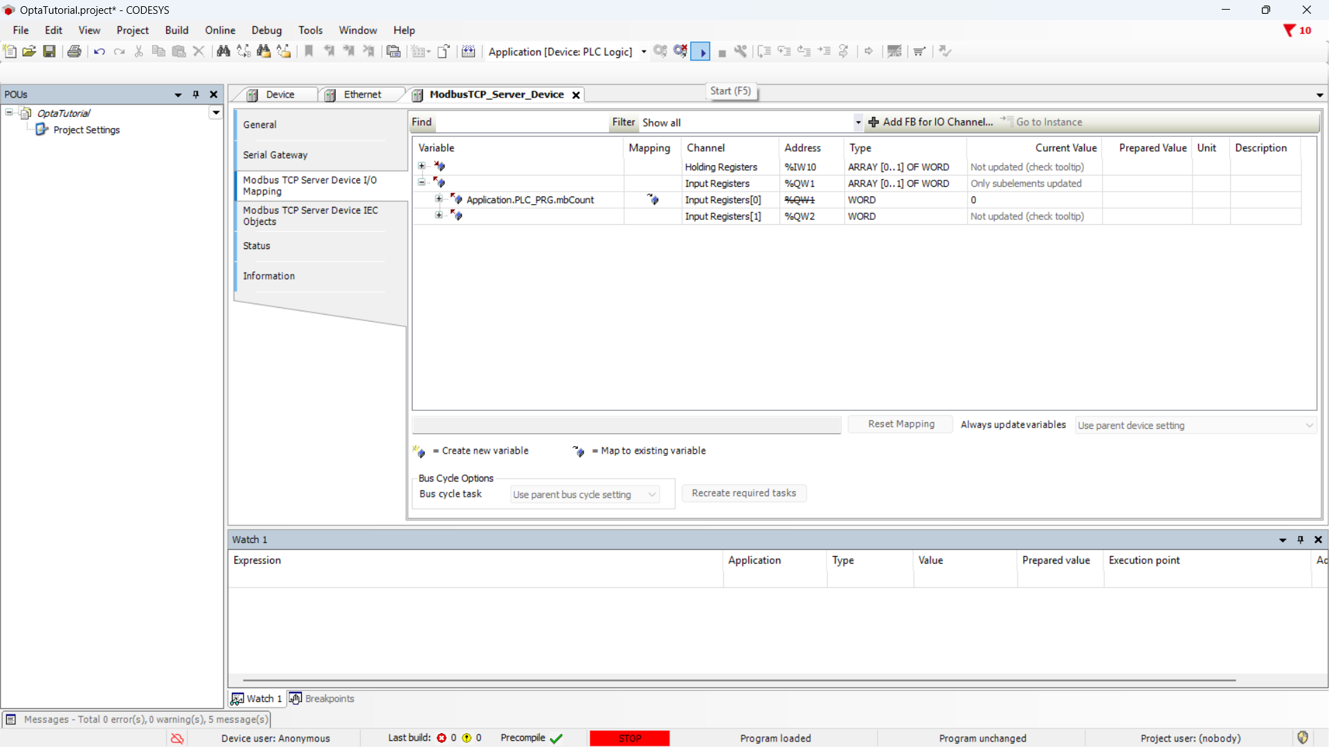
The ModbusTCP_Server_Device tab shows the real-time value of the counter
written in the Input Register.
Instructions to create a Modbus TCP client
As mentioned previously, for this tutorial we have verified the system using a Kinco GR070E HMI and a Weintek MT8051iE HMI. To end this tutorial, we will implement a program for each HMI that allows the reader to display the counter value read from the Finder OPTA via Modbus TCP on the screen of the panel.
It is the reader's responsibility to ensure that the HMI is powered correctly and that it is connected via Ethernet to the Finder OPTA, and to the computer from which it is being programmed.
Program for HMI Kinco GR070E
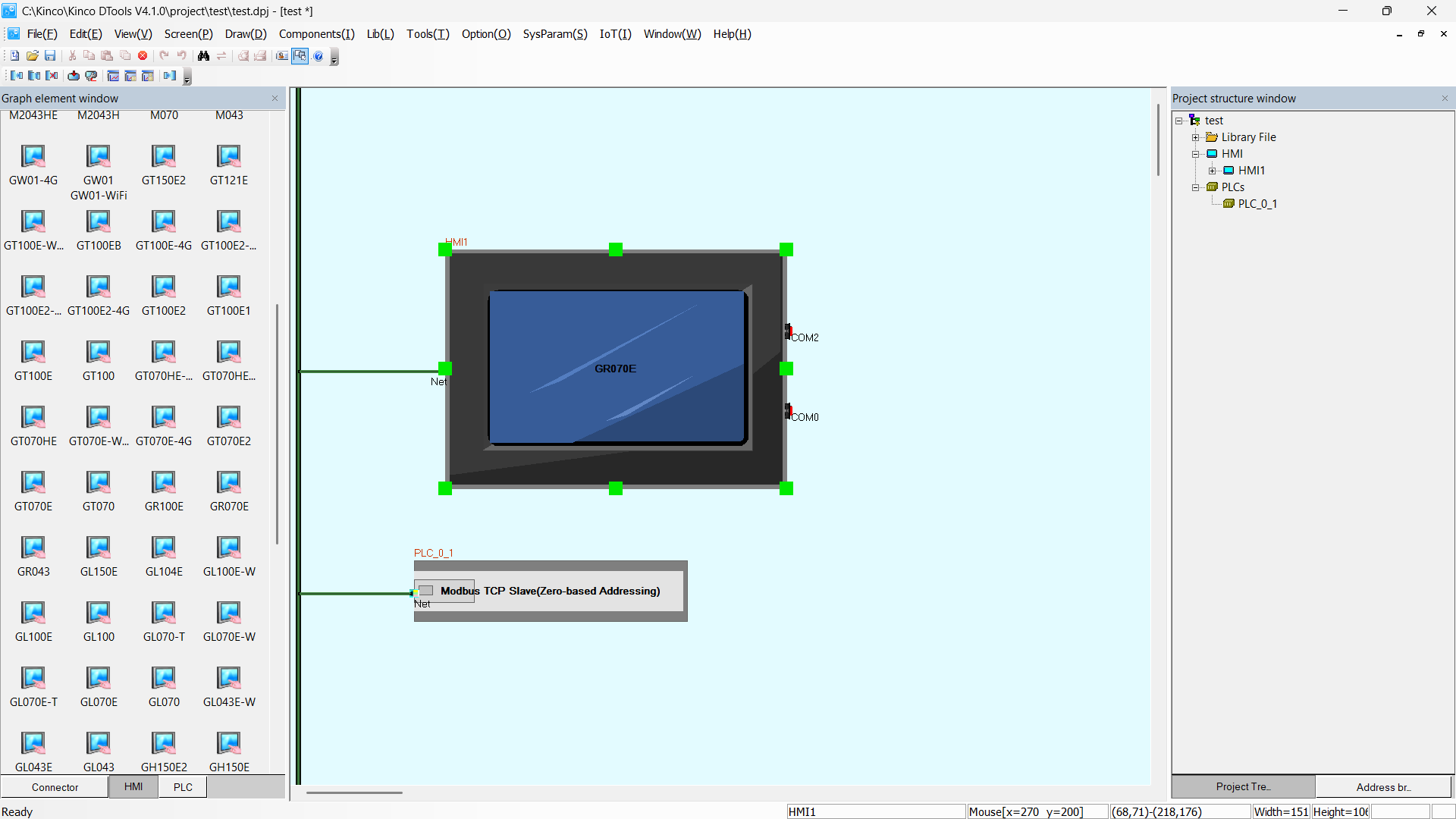
Create a new project using the Kinco DTools IDE and add the GR070E HMI to
the project: from the side panel named HMI, find the correct model and drag
it into the main project screen.
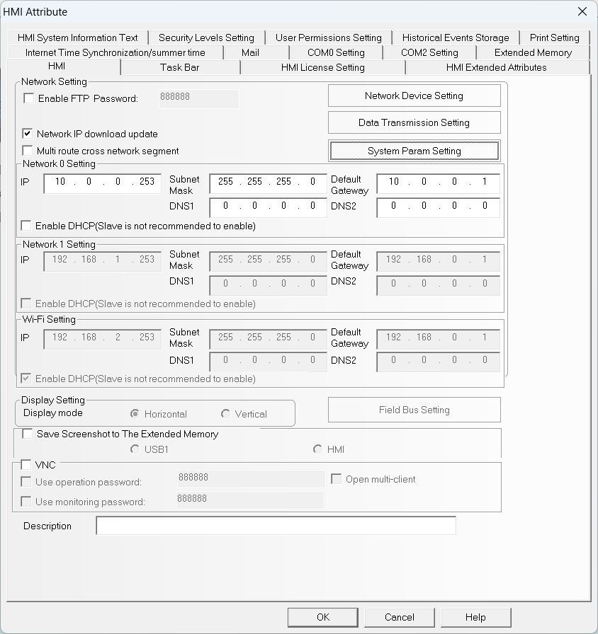
Double-click the panel icon and enter the network configuration.
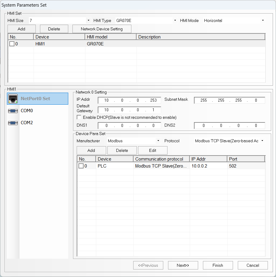
From the same screen, click on System Param Settings and add
a device with manufacturer Modbus and protocol Modbus TCP Slave (Zero-based Addressing). This device represents the Finder OPTA,
so we will configure its network with the same parameters we specified
in CODESYS:
- IP Address:
10.0.0.2. - Port number:
502. - Station number:
1.
Once the configuration is complete, the device will appear in the list with its own configuration.
Close the configuration screen by clicking Finish and then Ok. At this
point, you will see your HMI and the Modbus TCP server configured and connected.
From the right-side panel expand the HMI > Frames section and double-click
on Frame0. Select a Number Component element and drag it into the graphical
elements grid.
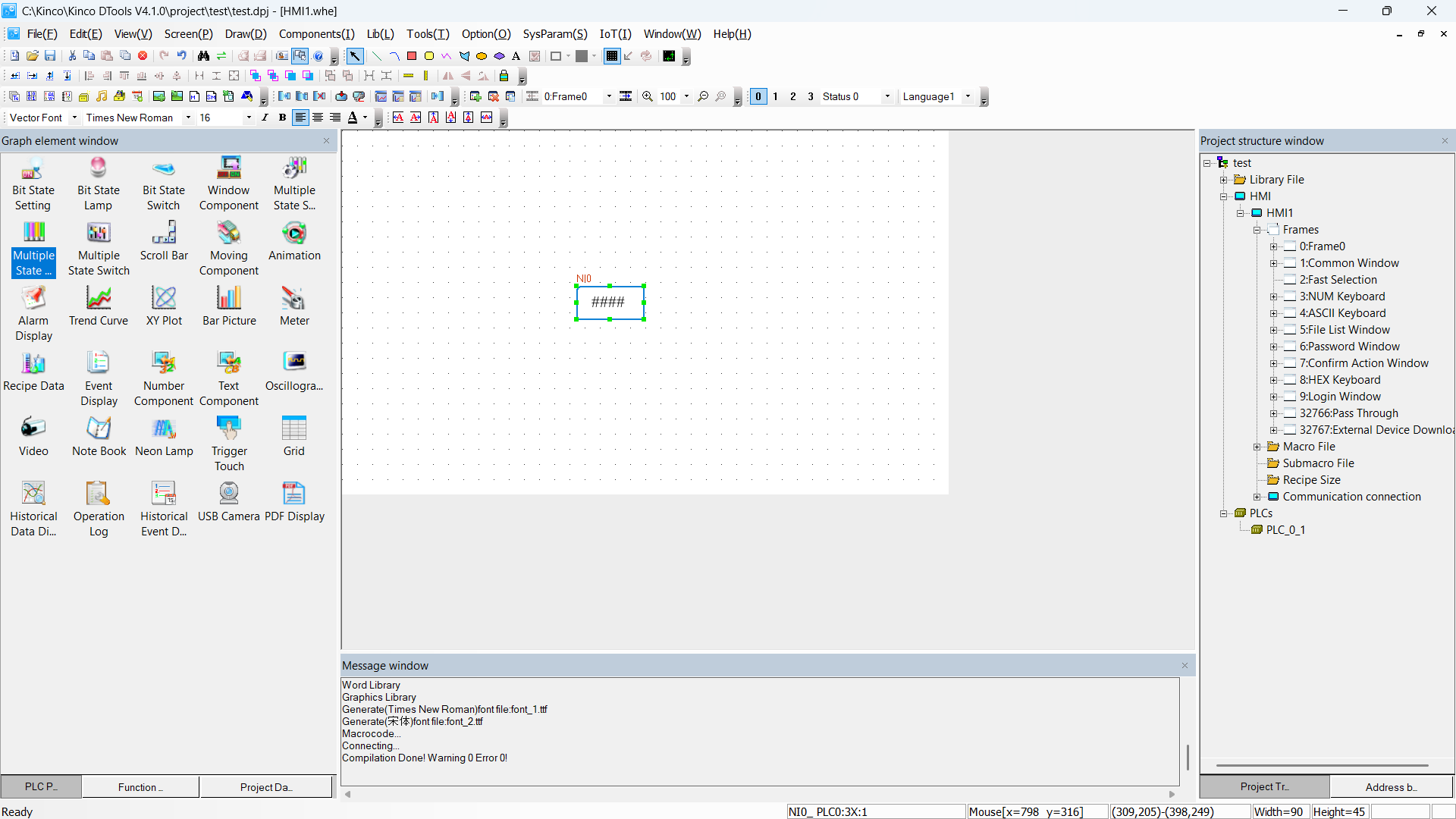
Double-click on the component you just created and configure it with the following parameters, which allow us to read an Input Register at address 1 of the Modbus TCP server and display its value inside the numeric component.
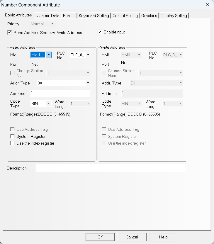
Now all that is left is to confirm the configuration by clicking OK
and then press the Download button to download the program to the panel.
Make sure the network configuration is as shown in the figure, otherwise set it
by clicking Set.
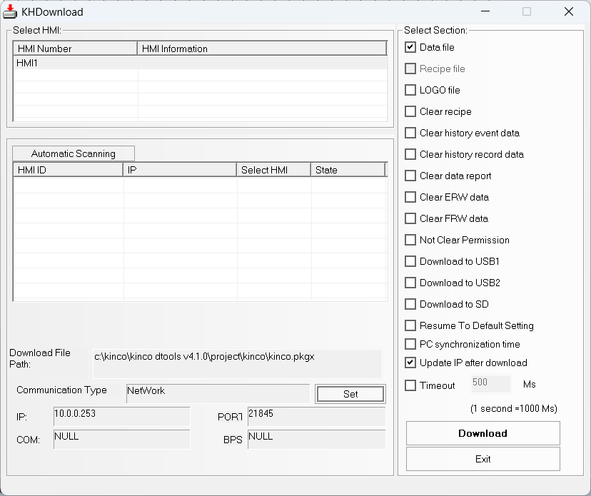
Click Download and wait: when the program has been downloaded to the HMI,
the panel will display the counter value read from the Finder OPTA.
Program for HMI Weintek MT8051iE
Create a new project using the EasyBuilder Pro IDE
and select the MT8050iE / MT8051iE model.
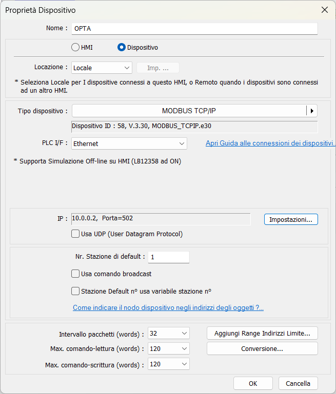
Next, the devices screen will appear: click on New device and add the
Modbus TCP server by setting the parameters as shown in the figure, according
to what was configured in CODESYS.
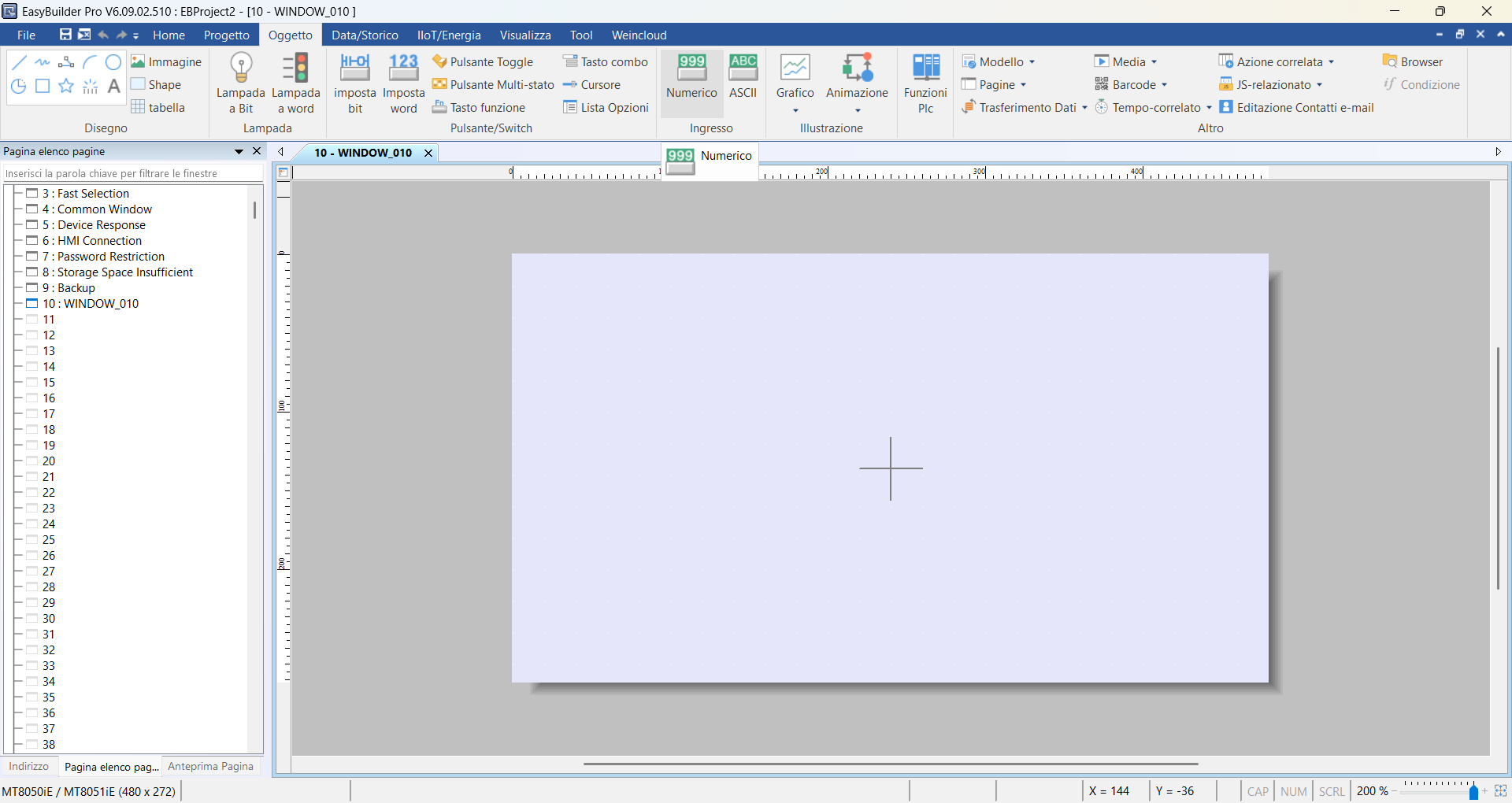
Click on the Object menu and add a Numeric component.
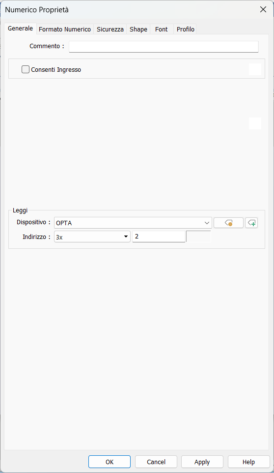
Set the following configuration to read an Input Register at address
1 of the Modbus TCP server and display its value inside the numeric
component. Note that - unlike the Kinco HMI - the Weintek HMI always counts
addresses starting from 0, so we will be reading the second 3x address.
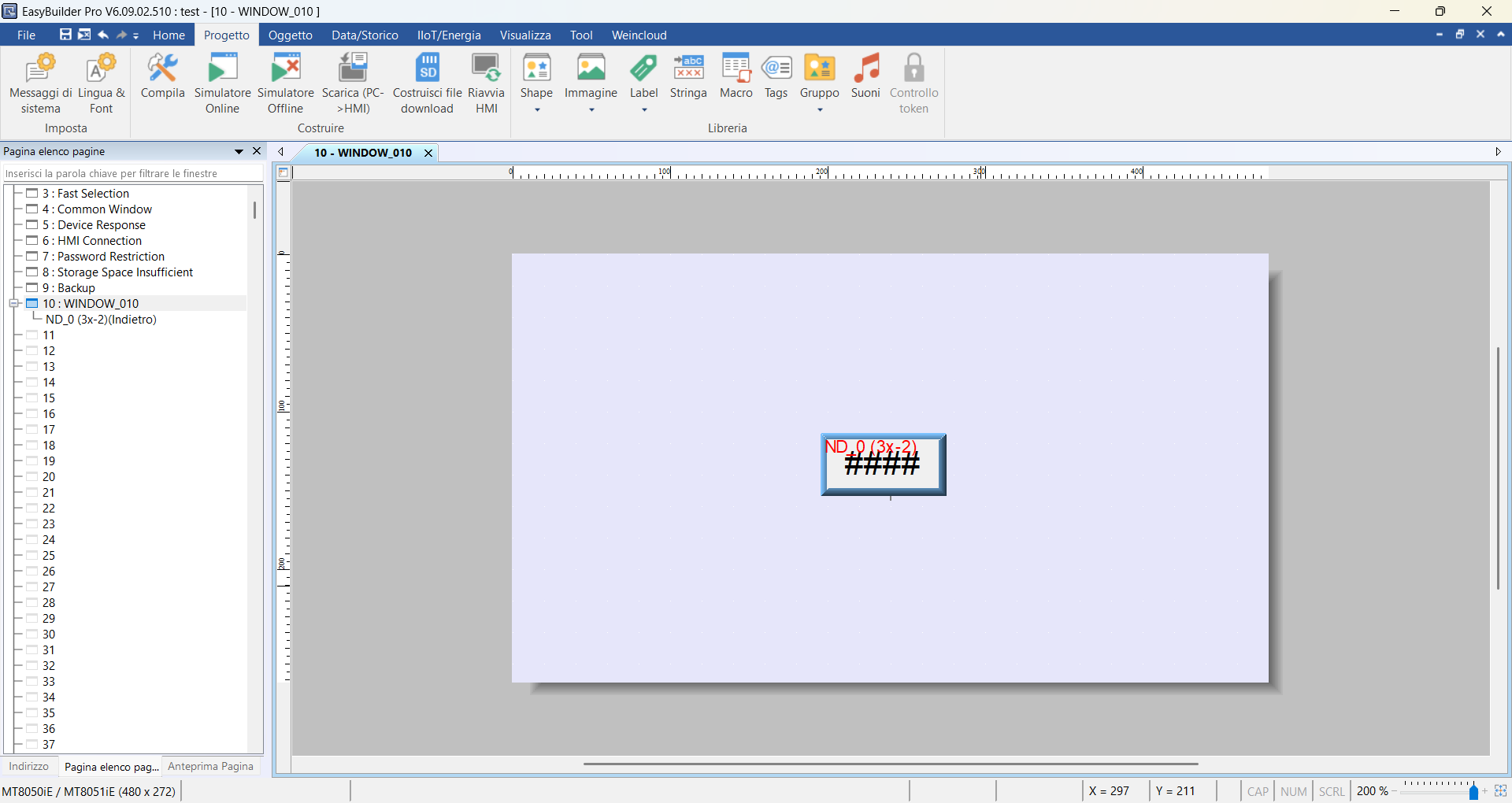
Click OK and then click the center of the screen to place the component.
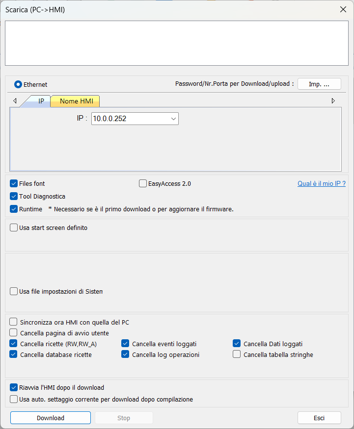
Click on the Project menu and then on Download (PC > HMI): at this point,
you will need to enter the IP address of your HMI, which must be on the same
subnet as the Finder OPTA. The IP address of the Weintek HMI can be configured
using the touch screen panel of the device, and in this case we set it to
10.0.0.252, so enter the same IP in the download screen.
Click Download and wait: once the program has been downloaded to the HMI,
the panel will display the counter value read from the Finder OPTA.
Conclusions
By following this tutorial you have configured Finder OPTA as a Modbus TCP server in CODESYS, exposing an internal variable through an Input Register and making it readable by any compatible HMI.
You have seen how to:
- Create a simple ST program to generate a value to be published.
- Configure the Ethernet port of Finder OPTA.
- Add and parameterize a Modbus TCP server in CODESYS.
- Map a PLC variable to a Modbus register.
- Read the value using two HMIs.
If you encounter difficulties during the implementation, carefully check the network configuration of the PLC and the HMI, the configured Modbus addresses, and the register mapping. An incorrect Modbus address configuration is the most frequent cause of incorrect readings or communication failure between Finder OPTA and the HMI.