Handleidingen en tutorials |
Overview
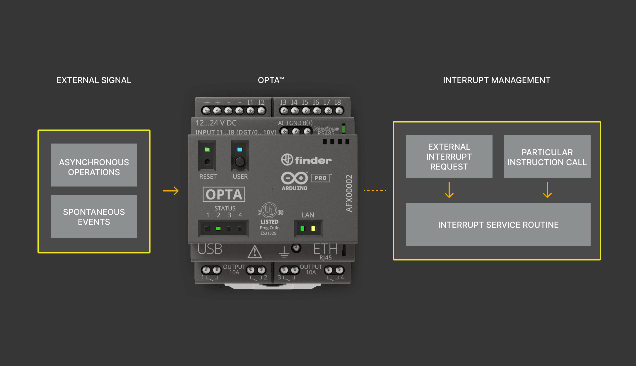
The Opta™ micro PLC is designed to operate in several industrial environments involving crucial processes. These processes require controllers to be responsive and precise to manage sensitive tasks and capable of handling large sets of conditions within defined parameters in real-time. Asynchronous operations or spontaneous events are the kind of process that requires immediate attention at a given moment. Therefore, interrupt management is critical to control and optimize these event classes.
The interrupt, a basic yet vital feature, is available on Opta™ to handle time-sensitive and unexpected events based on state changes. This tutorial will help you to implement interrupts on Opta™ using the Arduino programming language and the Arduino IDE.
Goals
- Learn how to configure an Opta™ to use interrupts
- Learn how to implement interrupts on Opta™
Required Hardware and Software
Hardware Requirements
- Opta™ Lite, Opta™ RS485, or Opta™ WiFi (x1)
- USB-C® cable (x1)
- +12-24 VDC/0.5 A power supply (x1)
Software Requirements
Interrupt Basics
Interrupts are execution requests triggered usually by a timed event or signal, which will pause the active process if the interrupt request is accepted under certain conditions, executing new high-priority commands immediately and returning to the main process as soon as possible. The Interrupt Service Routine, or ISR, is the handler that performs a specific instruction set whenever an interrupt is raised.
The handler can be defined to run particular instructions periodically, use external signals, or send an alert in case of a system failure. It is a function launched as a priority task among the other operations whenever a specific high-awareness state change occurs relative to an assigned trigger.
Interrupt Types
Interrupts are based on hardware and software events:
-
The hardware interrupt is an interrupt raised by a hardware signal sent from an external device. This interrupt class handles its asynchronously generated interrupt signal to synchronize it with the subsequent instructions of the interrupted device. For example, the button press can send a signal that represents the change in the hardware state to execute a task requiring immediate attention, such as an emergency stop alert.
-
The software interrupt is raised when the device itself is exposed to internally defined conditions or upon a particular routine call. It watches for special conditionals that create interrupts based on the present parameters. For instance, read and write operations of the storage device interacting with the controller driver is one example that involves software interrupt.
Interrupt Triggers
Interrupt signals must be set with appropriate triggers to create interrupt requests correctly, and they become critical when implemented on programmable logic controllers such as Opta™. Because it handles broad signal types, it is a good practice to understand which signal circumstances suit certain applications. Generally, they are Level-Triggered or Edge-Triggered interrupts. They are characterized as follows:
- Level-Triggered: This is when an interrupt has been requested with signals at a particular logic level, which can be either HIGH or LOW.
- Edge-Triggered: This is when an interrupt has been requested due to a signal at a specific transition level, which can be either RISING or FALLING edge. It can also be configured with CHANGE to interrupt whenever either signal transition has occurred.

Now that you have a better knowledge about interrupts, let’s see how to use interrupts with an Opta™ device.
Interrupts on Opta™
Opta’s analog/digital programmable inputs and user-programmable button are interrupt-capable; you can use them through the built-in functions of the Arduino programming language. To enable interrupts in your Opta’s analog/digital programmable inputs and user-programmable button it is important to do the following:
- Add the
attachInterrupt(digitalPinToInterrupt(pin), ISR, mode)instruction in your sketch’ssetup()function. Notice that thepinparameter can beA0,A1,A2,A3,A4,A5,A6,A7, orBTN_USER; theISRparameter is the ISR function to call when the interrupt occurs, and themodeparameter defines when the interrupt should be triggered (LOW,CHANGE,RISING, orFALLING).
Due to Opta’s microcontroller interrupt structure, terminals I1 (A0) and I4 (A3) interrupts cannot be used simultaneously to avoid operational issues. It is important to note that, despite this limitation, any other combination of inputs can be used for interrupt detection. However, this means that, at most, seven of the eight available inputs can be used simultaneously for interrupts, as combinations containing I1 and I4 are excluded from viable configurations.
Instructions
Setting up the Arduino IDE
This tutorial will need the latest version of the Arduino IDE. You can download the Arduino IDE here. Please check the Opta™ User Manual if it is your first time setting up the Opta™ with the Arduino IDE.
Example Setup
The example will try to keep the setup as simple as possible while maintaining the scalability of the feature on Opta™. The setup will use the programmable user button (BTN_USER) and A0-A1 inputs as interrupt pins. All available D0-D3 relays will be configured as outputs, and status LEDs will indicate the corresponding contact state.
Please refer to the following diagram to have an overview of the inputs and outputs position of the example model.

Example Overview
The example will showcase different interrupt routines for Opta™ using two scenarios:
- The
BTN_USERis the user-programmable button that will be used for the interrupt to simulate asynchronous events. The corresponding interrupt will make a relay and corresponding status LED state switch in a sequence based on its present state. - The
A0andA1inputs will be open to external devices that send signals periodically, and it will make an interrupt on the signaled pin. TheA0will be in charge of theD0andD1relays, while theA1will control theD2andD3relays.
These tasks will help you test multiple interrupt schemes combined with Opta™ PLC’s onboard relays and status LEDs. The following section will highlight the details of interest of the example code to help you understand it with ease.
Example Description
When working with interrupts, it is crucial to designate the interrupt variables as volatile so that they can be used by both the ISR function and the main program. In this case, counter will keep the number of BTN_USER presses and relayLedState to track the status LED of the corresponding relay. The boolean variables relCntState, batchState01, and batchState23 will be used to control the conditional flag when its respective interrupt is called.
volatile unsigned int counter, relayLedState {};
volatile bool relCntState = false;
volatile bool batchState01 = false;
volatile bool batchState23 = false;
The relays and corresponding status LEDs are defined in an array, including their status. Using the array provides the advantage of managing and calling the data flexibly.
int idx{ 0 };
int relays[]{ D0, D1, D2, D3 };
int leds[]{ LED_D0, LED_D1, LED_D2, LED_D3 };
bool statuses[]{ true, true, true, true };
The setup() will define the relay and status LED outputs, as well the inputs that will be used to attach to interrupt cases. The attachInterrupt() function configures the inputs as interrupts with its trigger method and connects to the defined ISR functions that can be found later in the example description.
For more information about attachInterrupt() function, please check here. You will also be able to read briefly more information about interrupts.
Thus, all the defined input pins are set as interrupt pins with their dedicated ISR functions and are programmed to trigger with a RISING signal. This way, every time one of the pins goes from LOW to HIGH (rising signal), the ISR or callback function will be executed.
void setup(){

  ...

  // Output Configuration
  for (int i = 0; i < 4; i++) {
    pinMode(relays[i], OUTPUT);
    pinMode(leds[i], OUTPUT);
  }

  // Input Configuration
  pinMode(A0, INPUT);
  pinMode(A1, INPUT);
  pinMode(BTN_USER, INPUT);

  // Interrupt configuration
  attachInterrupt(digitalPinToInterrupt(BTN_USER), relayCounterISR, RISING);
  attachInterrupt(digitalPinToInterrupt(A0), batch01_ISR, RISING);
  attachInterrupt(digitalPinToInterrupt(A1), batch23_ISR, RISING);
}
The loop() will be running tasks that are to execute based on BTN_USER or A0-A1 interrupts. It will also be checking and keeping the number of button presses that represent interrupts generated by the BTN_USER button.
void loop(){

  if (millis() > printNow) {
      Serial.print("Presses: ");
      Serial.println(counter);

      printNow = millis() + printInterval;
  }

  // For USR_BTN interrupts
  relayLinearCounter();

  // For A0 & A1 interrupts
  relayBatchInverter();
}
The relayLinearCounter() function runs a linear sequence for turning on and off the D0 to D3 relays with their corresponding status LEDs based on the interrupt triggered each time BTN_USER is pressed.
The counter and relayLedState variables are used to track the total number of BTN_USER triggered interrupts, which also represents the number of button presses and currently shifted relay status. The relCntState is used as a gatekeeper instance based on the BTN_USER interrupt request since it is an active function inside the loop() function.
/**
  Function to manage relay and status LED state in linear sequence based on BTN_USER interrupt.
*/
void relayLinearCounter(){
  if (relCntState == true){
    if (counter > 4){
      relayLedState = counter % 4;

      if (relayLedState == 0){
        relayLedState = 4;
      }
    } else {
      relayLedState = counter;
    }

    Serial.print(F("Triggered Relay: "));
    Serial.println(relayLedState);
    Serial.print(F("Counter Status: "));
    Serial.println(counter);

    // Array indexes start at 0
    idx = relayLedState - 1;
    relayStateHandler(idx);

    relCntState = false;
  }
}
The relayBatchInverter() function checks to invert a relay batch and its corresponding status LEDs based on A0 and A1 interrupt pins. The A0 controls the batch of relays D0 and D1, while The A1 controls D2 and D3 relays.
Each input has an ISR function conditioned with batchState01 and batchState23 boolean variables. When either pin is triggered with an interrupt signal, it will invert the state of the corresponding relay batch based on present relay states.
/**
 Function to handle relay and status LED states based on A0 & A1 interrupts to invert its defined states in batch.
*/
void relayBatchInverter(){
  if (batchState01 == true){
    Serial.println(F("A0 interrupt: Relay Batch 0 & 1"));
    for (int i = 0; i < 2; i++){
      relayStateHandler(i);
    }
    batchState01 = false;
  }

  if (batchState23 == true){
    Serial.println(F("A1 interrupt: Relay Batch 2 & 3"));
    for (int j = 2; j < 4; j++){
      relayStateHandler(j);
    }
    batchState23 = false;
  }
}
The relayStateHandler() function manages the relay status and is implemented as a complementary function. The digitalWrite() function will use a special conditional that stores the applied state in a variable called status.
It will seek the corresponding relay and compare its stored status to shift its state in a more automated way. This is a practical method to avoid writing the same lines of code in different parts of the sketch and can help to maintain a cleaner code structure using a single function with an argument to process the data.
/**
  Function to handle relay and status LED state by receiving relay designation.
*/
void relayStateHandler(int relayID){
  // Get current status
  auto status = statuses[relayID] ? HIGH : LOW;

  // Apply new status to the outputs
  digitalWrite(relays[relayID], status);
  digitalWrite(leds[relayID], status);

  // Invert the statuses array to be updated
  statuses[relayID] = !statuses[relayID];
}
These are all the ISR functions that help to shift relay states within the corresponding process whenever an interrupt has occurred. These functions are kept as short as possible to maintain quick responses for interrupts that can happen at any time.
For good practice, please do not use delay() inside these functions as it might cause erratic behaviors, and use it as a quick state modifier to be used with functions that may be running continuously.
/**
  ISR functions. Below are related inputs with respective ISR function.
  - BTN_USER: relayCounterISR()
  - A0: batch01_ISR()
  - A1: batch23_ISR()
*/
void relayCounterISR(){
  counter++;
  relCntState = true;
}

void batch01_ISR() {
  batchState01 = !batchState01;
}

void batch23_ISR() {
  batchState23 = !batchState23;
}
Full Example Code
You can access the complete example code here. After extracting the compressed file, you will be able to upload and test it out with your Opta™ device.
Testing Interrupt Example
You will be able to observe the following results when testing if you were able to upload the example code correctly to the Opta™.
- You will be able to observe that the
D0-D3relays are turning on in sequence and turning off in the next succession linearly as you press theBTN_USERbutton. The sequence then will repeat, and the counter will keep a record of the number of interrupts caused byBTN_USERbutton press, and currently actuated relay viarelayLedState. - If you send feedback on either
A0orA1input with a rising edge signal, it will apply state inversion on top of the actual relay states as a result of the interrupt. Thus, you will observe theD0andD1relays invert their states if the interrupt was triggered onA0; whileA1will do the same job, but onD2andD3relays.
Hence, your Opta™ is processing based on an asynchronous interrupt generated by BTN_USER button while A0-A1 are in charge of the interrupts generated periodically by an external device.
Conclusion
In this tutorial, you have learned to enable and use interrupts on Opta™. On top of it, with the supplied example, you have tested Opta™ with multiple interrupt cases by using an integrated user-programmable button and signal sources from external devices, along with the Opta™ PLC’s hardware features as onboard relays and status LEDs. Using the example of this tutorial as reference, now you can implement interrupts in your own professional solutions.
Next Steps
Now that you are familiar with interrupts on the Opta™, take a look at the following documentation to learn more:
- Take a look at the Opta™ User Manual to get a better overview of the features of Opta™
- If you wish to incorporate Wi-Fi®/Bluetooth® Low Energy in your Opta™ solutions, have a look at connectivity tutorial