Guide and Tutorial |
Introduction
The Opta™ can be an irreplaceable support for home energy management. Getting information on instantaneous electrical consumption and interacting with the customer’s consumption plan, daily usage statistics, and seasonal forecasts can help in planning and managing electrical devices to optimize energetical efficiency. Always be connected and informed by integrating the Arduino Cloud, and add self-adjustment capability by monitoring and logging electrical statistics along with the option to operate the connected devices on-demand based on pre-set triggers.
As the industry shifts towards Industry 4.0, also known as the Industrial Internet of Things (IIoT), the focus is on improved energy management and the ability to operate devices on-demand within power grids. This transition promises significant cost savings and enhanced production performance. Opta™ prioritizes security, featuring elements that ensure data integrity, encryption, and secure certificate storage. This makes it a suitable IoT node for creating a private and secure IIoT network.
Goals
This application note shows an example of an energy management system, leveraging Opta™ and Arduino Cloud capabilities to perform the following operations:
- Allow Opta™ to receive and process remote actuation commands from the Arduino Cloud
- Enable Opta™ to control devices based on the user’s energy consumption patterns and the energy available from solar panels or any other power sources
- Automate the operation of home appliances by considering user demands, power availability, and energy efficiency
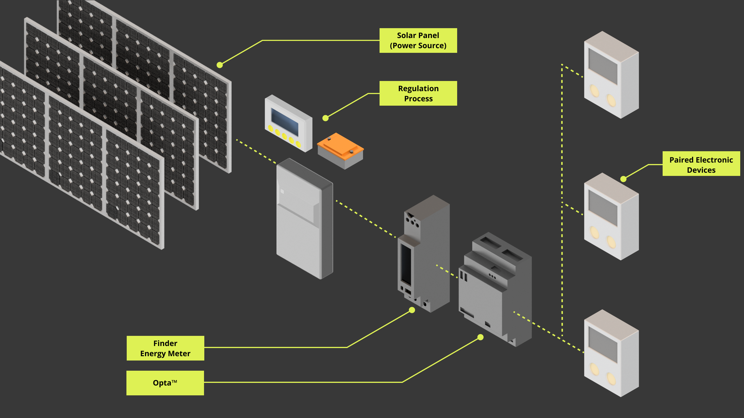
Below is a visual representation of the intended application:
Hardware and Software Requirements
Hardware Requirements
- Opta™ PLC with RS-485 support: Opta™ Plus, or Opta™ Advanced (x1)
- USB-C® cable (x1)
- 7M.24 Energy meter (x1)
- Solar panel with respective system (Controller, battery, and inverter) or similar power system
- Domestic appliances or devices of interest
- RS-485 connection wire as recommended by the standard specification (x3):
- STP/UTP 24-18AWG (Unterminated) 100-130 Ω rated
- STP/UTP 22-16AWG (Terminated) 100-130 Ω rated
Software Requirements
- Arduino IDE 1.8.10+, Arduino IDE 2.0+, or Arduino Cloud Editor
- If you choose an offline Arduino IDE, you must install the following libraries:
ArduinoRS485,ArduinoModbusandScheduler. You can install those libraries via the Library Manager of the Arduino IDE. - For the Wi-Fi® connectivity feature of Opta™, we will use Arduino Cloud; you will need to create an account if you still need to create one.
- Opta™ Energy Manager Example Code
Hardware Setup Overview
The electrical connections of the intended application design are shown in the diagram below:
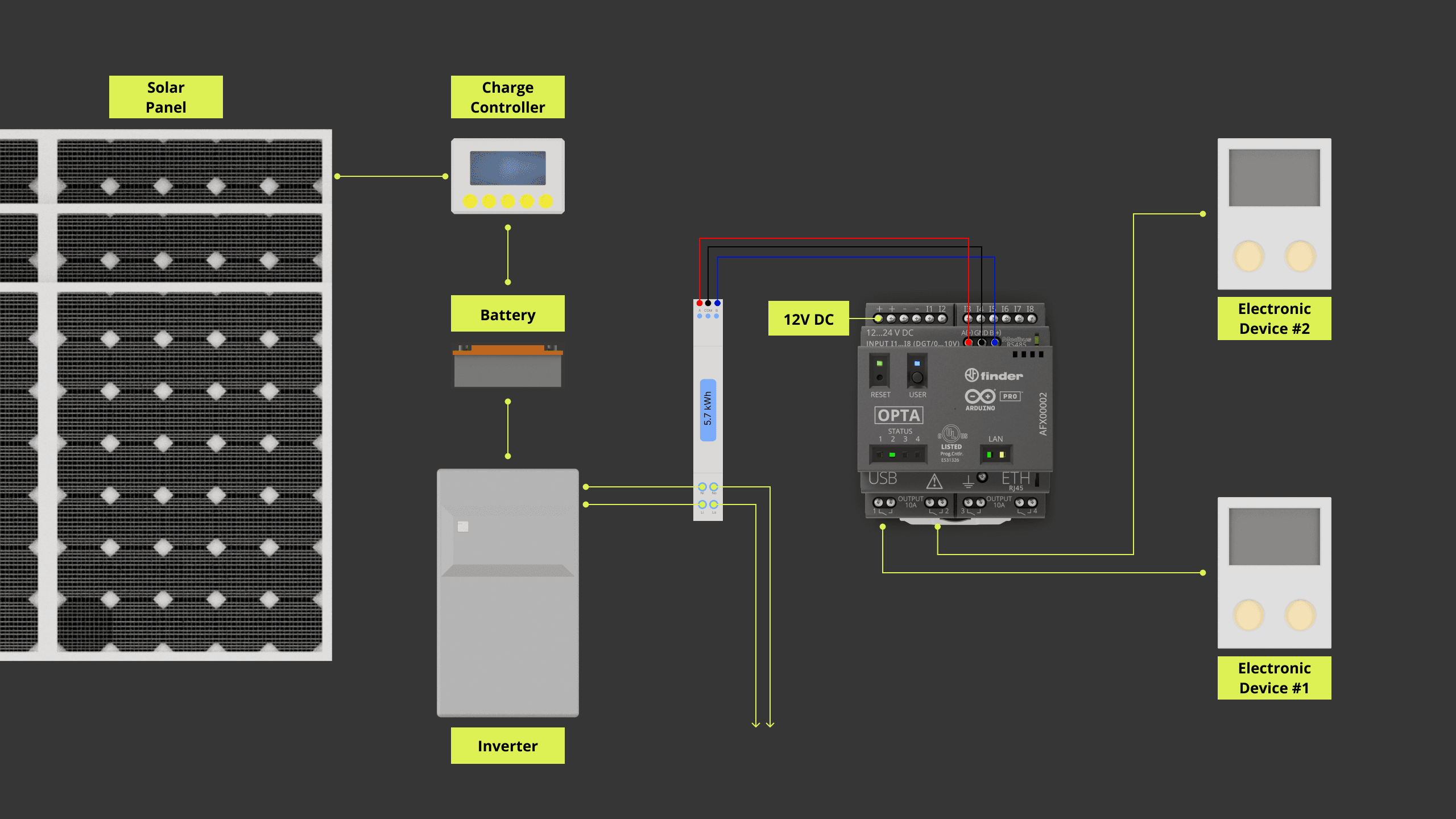
The Opta™ system will access real-time consumption details from the energy meter, using the Modbus RTU over the RS-485 interface. Power from the solar panels undergoes multiple processes before it reaches the energy meter. Household appliances can be managed using the Opta™ system’s built-in relay functions. It is also worth noting that other power sources can replace the solar panels.
Opta™ Energy Management Model Description
The main role of Opta™ is to efficiently handle power, using data from the energy meter linked to the solar panel as its basis. It fetches and processes data from the energy meter, estimating real-time consumption based on the meter’s thresholds and the current power output of the solar panel.
For this application, we are using the 7M.24 energy meter model from Finder. You can access its datasheet here. This model communicates via the Modbus RTU on the RS-485 interface. The relay functions of Opta™ will operate the relevant household appliances. To gather data and oversee power allocation, Opta™ carries out the following steps:
- Procure voltage and current readings from the energy meter.
- Gather three types of power readings from the energy meter: Active Power Total – Pt (
W), Reactive Power Total – Qt (var), and Apparent Power Total – St (VA). - Organize the collected data on Voltage, Current, and Power (Active, Reactive, and Apparent) into various categories to represent the Actual, Average, Maximum, and Minimum values of each.
- Access the Energy Counter figures in
Whandvarhunits. - Distribute power optimally to regulate selected household appliances, based to the user’s energy profile.
While all these processes are handled by Opta™ locally, it is also connected to the Arduino Cloud through Wi-Fi®. This connection allows users to view their energy usage and remotely control connected devices via the Arduino Cloud.
Opta™ Energy Management Example Code
The provided code showcases the capabilities of Opta™ as described earlier. It is worth noting that some code functions are generated by the Arduino Cloud during dashboard configuration. For immediate access to the full example, the files can be downloaded here. We will now delve into key code components to break down how the example code works.
The code requires the inclusion of specific headers. These headers enable the RS-485 interface, the Modbus RTU protocol, the Arduino Cloud connection, and the scheduler. The scheduler oversees data exchange through the RS-485 interface using the Modbus RTU protocol. Moreover, it includes the parameters essential for stable communication, adhering to Modbus RTU standards.
#include "stm32h7xx_ll_gpio.h"
#include "thingProperties.h"
#include <ArduinoModbus.h>
#include <ArduinoRS485.h>
#include <Scheduler.h>

#define F7M24 0x21
#define pause_trigger 15

// Energy Meter Parameters
float V_actual, V_avg, V_max, V_min;
float A_actual, A_avg, A_max, A_min;
float W_actual, W_avg, W_max, W_min;
float Var_actual;
float Va_actual, Va_avg, Va_max, Va_min;
float Wh_packet, Varh_packet, Wh_Abs_packet;

typedef struct uPWR_STRUCT {
  float uV_code;
  float uW_code;
  float uWh_code;
} PWR_STRUCT;
PWR_STRUCT user_profile;

/**
  ======================= IMPORTANT =======================
  Before using the system, the following parameters MUST be defined:

  - operation_safety_margin: Multiplier indicating safety margin. E.g., 1.1 implies a 10% headroom.
  - estimated_max_power: Expected maximum power (in Watts) under which the network will operate.
  - estimated_max_energy: Expected maximum active energy limit (in Wh) for the network.
  - Device_1_Limiter & Device_2_Limiter: Upper limit current (in Amperes) and power (in Watts) for Device 1 & 2 respectively.
  - Device_1_CompRef & Device_2_CompRef: Energy meter parameters required for accurate system operation.
*/
float operation_safety_margin = 1.1;
float estimated_max_power = 220;
float estimated_max_energy = 2880;
float Device_1_Limiter = 1;
float Device_2_Limiter = 100;
float Device_1_CompRef = A_actual;
float Device_2_CompRef = W_avg;
/*
  It is CRUCIAL to set these parameters accurately to ensure safe and correct operation of the system.
  =========================================================
*/

constexpr auto baudrate { 19200 };

// Calculate preDelay and postDelay in microseconds as per Modbus RTU Specification
// MODBUS over serial line specification and implementation guide V1.02
// Paragraph 2.5.1.1 MODBUS Message RTU Framing
// https://modbus.org/docs/Modbus_over_serial_line_V1_02.pdf
constexpr auto bitduration { 1.f / baudrate };
constexpr auto preDelayBR { bitduration * 9.6f * 3.5f * 1e6 };
constexpr auto postDelayBR { bitduration * 9.6f * 3.5f * 1e6 };
It is vital to configure the user parameters correctly to ensure appropriate system operation. Such parameters are:
-
operation_safety_margin: This is the safety margin multiplier factor. It is expressed in decimal format. For instance, to have a 20% safety buffer, the input should resemble1.2. -
estimated_max_power: It is the anticipated maximum power (measured in Watts) under which the network will operate. It serves to set a benchmark average power based on user input, which is then compared to the energy meter reading. This helps verify if the network is running in line with the desired electrical attributes set by the user. -
estimated_max_energy: Similar toestimated_max_power, this parameter marks the forecasted maximum active energy limit (in Wh) for the network. Its role is to ensure that the network remains stable in delivering consistent power to the connected devices. -
Device_X_Limiter: This sets the maximum limit for a chosen parameter for devices 1 & 2. Its definition should align with that of theDevice_X_CompRef. -
Device_X_CompRef: It is the reference value obtained from energy meter used to determine whether the device, considering priority parameter type, can be activated for accurate system operation.
For a deeper understanding of implementing Modbus RTU with Opta™, consider the tutorial Getting Started with Modbus RTU on Opta™.
The method relay_Trigger() performs a straightforward comparison between a desired target and a required target. Based on this comparison, it outputs a signal to activate a relay. It will also help the user know if the system is at stable capacity or having possible electrical disturbances that may cause unstable operation.
The user specifies the desired target value, which indicates the optimal threshold limit for the relay’s activation to maintain stable operation. On the other hand, the required target signifies the current power or other relevant electrical parameter reading introduced as an argument from the user.
It works as a two-flag condition, using the safety margin percentile to ensure electrical headroom is available without putting undue strain on the system. An example metric obtained from the energy meter for this purpose is W_actual, which represents the real-time total active power at the time of inquiry.
The user_profile.uV_code defines the operational buffer in terms of percentage. This is the safety margin multiplier factor derived from the user’s profile. For instance, setting the margin at 10% as 1.1 within the consumption_profile() method offers a safety overhead headroom. This method’s parameters come preset but can be adjusted later via the Arduino Cloud dashboard.
The relayTarget defines the output port prompted under certain activation conditions.
/**
  Control the relay output based on the user (consumption) profile input and configured power/energy target.

  @param desired_target Desired resource required to run the connected device on the relay.
  @param req_target Minimum resource required to run the connected device on the relay.
  @param relayTarget Relay to activate or deactivate.
  @return Returns 0 or 1, representing HIGH state for 1 and LOW state for 0.
*/
uint8_t relay_Trigger(int desired_target, int req_target, pin_size_t relayTarget) {
  bool isStable = (desired_target >= req_target) && (desired_target > (req_target * user_profile.uV_code));
  digitalWrite(relayTarget, isStable ? HIGH : LOW);
  Serial.print(F("Energy Manager: "));
  Serial.print(isStable ? F("Stable operation margin") : F("Unstable / possible overload"));
  Serial.print(F(" - Turning "));
  Serial.print(isStable ? F("ON: ") : F("OFF: "));
  Serial.println(relayTarget);

  return isStable ? 1 : 0;
}

/**
  Initial user profile setup.

  @param init_OperMargin  System operation margin for power budget represented in percentage.
  @param init_Watt  User defined Wattage limit for the system.
  @param init_WhCon User defined Energy consumption limit for the system.
  @return none
*/
void consumption_profile(uint32_t init_OperMargin, uint32_t init_Watt, uint32_t init_WhCon){
  uOperMargin = init_OperMargin;
  user_profile.uV_code = uOperMargin;

  uWatt = init_Watt;
  user_profile.uW_code = uWatt;

  uWhCon = init_WhCon;
  user_profile.uWh_code = uWhCon;
}
The function energy_distro_ctrl() uses energy meter data and user inputs from the Arduino Cloud to manage connected devices, offering options to override relay activation and monitor the system’s power capacity. Its decisions are mainly based on two conditions related to energy and power.
This ensures that devices operate when energy consumption is within a range that is 10% below the maximum safe operation level. The handleDevice() function streamlines parameter adjustments and troubleshooting for each device state, facilitating desired relay activation.
If the average power demand surpasses the predefined user profile threshold, the system will send an alert to the user. This application note takes into account specific data from the devices used, serving as a proof of concept for this scenario.
The Device #1 is configured for low-power devices that need a consistent current or the existing power to switch on securely. Users also have the option to control it remotely.
The Device #2 caters to devices with higher power demands. It will begin its operations if the current or average power available meets the specified power requirement.
/**
  Handler functions for energy_distro_ctrl() function
*/
bool handleDevice(float threshold, float parameter_reference_data, int pin) {
  bool deviceFlag = relay_Trigger(threshold, parameter_reference_data, pin);
  if (!deviceFlag) {
      if (relay_Trigger(threshold, W_actual, pin)) {
          Serial.println(deviceFlag == Device_1_f ? F("Energy Manager: Secondary condition pass, may be unstable") : F("Energy Manager: Secondary Power condition pass"));
      } else {
          Serial.println(F("Energy Manager: Insufficient resource"));
          digitalWrite(D0, LOW);
      }
  } else {
      Serial.println(F("Energy Manager: Conditions green"));
  }
  return deviceFlag;
}

/**
  Monitors and uses the user defined profile and retrieved information from Energy meter to manage connected devices of interest.

  @param Wh_packet Retrieved energy information from Energy meter in unit of [Wh].
  @param Device_#_f Device flag controlled by relay_Trigger() function. # specifies device number or designation.
  @param directOverride1 Direct override flag for Device #1 controlled via Cloud.
  @param W_avg Average power information retrieved from Energy meter.
  @param Device_X_Limiter User defined upper limit value for selected device parameter.
  @param Device_X_CompRef User selected Energy Meter parameter reading to be compared as a reference for device actuation and system behavior.
*/
void energy_distro_ctrl() {
  if (Wh_packet != 0) {
      uWhOpta = Wh_packet;
  } else {
      Serial.println(F("Energy Manager: Energy information recollection stand-by"));
      return;
  }

  if ((Wh_packet * user_profile.uV_code) <= user_profile.uWh_code) {
      Device_1_f = handleDevice(Device_1_Limiter, Device_1_CompRef, D0);
      Device_2_f = handleDevice(Device_2_Limiter, Device_2_CompRef, D1);
  } else {
      digitalWrite(D0, LOW);
      digitalWrite(D1, LOW);
      Serial.println(F("Energy Manager: Energy consumption is high! - Warning"));
  }

  if (directOverride1) {
      Serial.println(F("Energy Manager: Direct Override Request Received"));
      digitalWrite(D0, HIGH);
  }

  if ((W_avg * user_profile.uV_code) > user_profile.uW_code) {
      Serial.println(F("Energy Manager: Average Power is above profile limit! - Warning"));
      Serial.println(W_avg * user_profile.uV_code);
  }
}
The energy meter contains multiple register addresses that provide a broad spectrum of electrical data. In this application, we will focus on the following key elements:
- Voltage (
V) - Current (
A) - Total Active Power (
W) - Total Reactive Power (
var) - Total Apparent Power (
VA) - Energy measured in both
Whandvarh - Total Absolute Active Energy (
Wh)
The information will be categorized, if applicable, as:
actual: Represents the captured real-time data.average: Represents the mean data value over the operation duration.maximum: Represents the peak data value observed during active operation.minimum: Represents the lowest data value detected throughout active operation.
/**
  Requests and retrieves actual electrical, and power information from Energy meter over Modbus RTU protocol.
*/
void modbus_com_actual(){
  // Actual Measurements
  // Voltage (V)
  V_actual = getT5(F7M24, 30107);

  // Current (A)
  A_actual = getT5(F7M24, 30126);

  // Active Power Total - Pt (W)
  W_actual = getT6(F7M24, 30140);

  // Reactive Power Total - Qt (var) (IEEE 754)
  Var_actual = getT_Float(F7M24, 32544);

  // Apparent Power Total - St (VA)
  Va_actual = getT5(F7M24, 30156);
}
/**
Requests and retrieves energy information from Energy meter over Modbus RTU protocol.
*/
void modbus_com_energy(){
// Energy
// Energy (Wh) - n1
Wh_packet = getT_Float(F7M24, 32752);
// Energy (varh) - n4
Varh_packet = getT_Float(F7M24, 32758);
// Total Absolute Active Energy (Wh)
Wh_Abs_packet = getT_Float(F7M24, 32760);
}To enable Modbus RTU on Opta™, use the RTU_Setup() function, which ensures proper initialization of the protocol.
/**
  Sets up Modbus RTU protocol configuration.
*/
void RTU_Setup(){
  Serial.println("Energy Management - Modbus RTU Client");

  RS485.setDelays(preDelayBR, postDelayBR);

  // start the Modbus RTU client
  // 7M.24 Energy meter specifies 19200 of default baudrate and 8N2 frame
  if (!ModbusRTUClient.begin(baudrate, SERIAL_8N2)) {
    Serial.println("Failed to start Modbus RTU Client!");
    while (1)
        ;
  }
}
The provided functions are designed for data retrieval from a target device via the Modbus RTU protocol. Each function is designed to fetch specific data types from the device using distinct register addresses.
By indicating the device and the register address, these functions simplify the process of accessing data from devices that communicate through Modbus RTU. We will employ these functions to extract data from the 7M.24 energy meter.
/**
Obtains T5 data type variable
@param dev_address Device address.
@param base_reg Register address.
*/
float getT5(int dev_address, int base_reg) {
ModbusRTUClient.requestFrom(dev_address, INPUT_REGISTERS, base_reg - 30000, 2);
while(!ModbusRTUClient.available()) {}
uint32_t rawreg = ModbusRTUClient.read() << 16 | ModbusRTUClient.read();
int8_t reg_exp = ((uint8_t*)&rawreg)[3];
uint32_t reg_base = rawreg & 0x00FFFFFF;
float reg = reg_base * pow(10, reg_exp);
return reg;
}
/**
Obtains T6 data type variable
@param dev_address Device address.
@param base_reg Register address.
*/
float getT6(int dev_address, int base_reg) {
ModbusRTUClient.requestFrom(dev_address, INPUT_REGISTERS, base_reg - 30000, 2);
while(!ModbusRTUClient.available()) {}
uint32_t rawreg = ModbusRTUClient.read() << 16 | ModbusRTUClient.read();
int8_t reg_exp = ((uint8_t*)&rawreg)[3];
int32_t reg_base = (int32_t)rawreg & 0x007FFFFF;
if(rawreg & 0x800000) {
reg_base = -reg_base;
}
float reg = reg_base * pow(10, reg_exp);
return reg;
}
/**
Obtains T2 data type variable
@param dev_address Device address.
@param base_reg Register address.
*/
float getT2(int dev_address, int base_reg) {
ModbusRTUClient.requestFrom(dev_address, INPUT_REGISTERS, base_reg - 30000, 1);
while(!ModbusRTUClient.available()) {}
int16_t rawreg = ModbusRTUClient.read();
return (float)rawreg;
}
/**
Obtains T_Float data type variable
@param dev_address Device address.
@param base_reg Register address.
*/
float getT_Float(int dev_address, int base_reg) {
ModbusRTUClient.requestFrom(dev_address, INPUT_REGISTERS, base_reg - 30000, 2);
while(!ModbusRTUClient.available()) {}
uint32_t rawreg = ModbusRTUClient.read() << 16 | ModbusRTUClient.read();
float reg;
memcpy(®, &rawreg, sizeof(float));
return reg;
}These functions aim to fetch and handle data types T5, T6, T2, and T_float.
T5: 32-bit Unsigned MeasurementT6: 32-bit Signed MeasurementT2: 16-bit Signed ValueT_float: 32-bit IEEE754 Floating-Point Single Precision Value
For incorporating or using 7M.24 energy meter parameters with different data types, refer to the Modbus Data Types section on page 19 of the 7M.24 Modbus protocol sheet.
The iot_cloud_setup() function serves as the connection bridge between the Arduino Cloud and Opta™. By grouping the processes into one task, the code is streamlined and easier to maintain.
/**
  Sets up configuration for Arduino Cloud
*/
void iot_cloud_setup(){
  // Defined in thingProperties.h
  initProperties();

  // Connect to Arduino Cloud
  ArduinoCloud.begin(ArduinoIoTPreferredConnection);

  /*
     The following function allows you to obtain more information
     related to the state of network and IoT Cloud connection and errors
     the higher number the more granular information you’ll get.
     The default is 0 (only errors).
     Maximum is 4
 */
  setDebugMessageLevel(2);
  ArduinoCloud.printDebugInfo();
}
The Opta™ will initialize the RS-485 interface and Modbus RTU protocol, the Arduino Cloud connection, and the scheduler to handle Modbus RTU protocol based communication with the 7M.24 energy meter. Analog and Digital I/Os are configured here as well.
The consumption_profile() chracterizes the headroom margin for operation, power, and energy limit. The parameters, set through operation_safety_margin, estimated_max_power, and estimated_max_energy, serve as the standard local configuration and can be accessed on the Arduino Cloud dashboard.
void setup() {
  // Initial Parameter
  directOverride1 = false;
  uWhOpta = 0;

  Serial.begin(9600);
  delay(1000);

  // Analog/Digital IO Port Configuration
  analogIO_Setup();
  digitalIO_Setup();

  // Modbus RTU Configuration
  RTU_Setup();

  // Status LED configuration;
  plc_led_Setup();

  // IoT Cloud Setup
  iot_cloud_setup();

  // Configures user profile and controlled device parameters
  consumption_profile(operation_safety_margin, estimated_max_power, estimated_max_energy);

  // Only for Device On State flag
  digitalWrite(LEDG, HIGH);

  // Scheduler -> ModBus
  Scheduler.startLoop(modbus_line);
}
The Opta™ will have the main loop() to prioritize tasks to communicate with Arduino Cloud and local processes. It will have the job of managing profile data and energy distribution control logic with Arduino Cloud instance updates. While the modbus_line() will focus on handling Modbus RTU protocol-based communication over the RS-485 interface.
The modbus_com_monitor() serves to display all the essential electrical information obtained via 7M.24 energy meter,
void loop() {
  // Cloud exchange
  consumption_var_container();
  ArduinoCloud.update();

  // Profile based energy management tasks
  energy_distro_ctrl();

  // Serial print of the data from the Energy Meter
  modbus_com_monitor();

  delay(500);
}

/**
  Dedicated function for scheduler to retrieve Energy meter's information over Modbus RTU protocol
*/
void modbus_line(){
  modbus_com_actual();
  modbus_com_avg();
  modbus_com_max();
  modbus_com_min();
  modbus_com_energy();
}
The header that includes the Arduino Cloud properties is outlined below. This file comes from the Arduino Cloud platform within the sketch’s workspace. It requires prior configuration of Opta™. Due to project specifications, these properties are subject to changes.
If Opta™ was configured to use Wi-Fi® connectivity as the network interface, the thingProperties.h header will resemble as follows.
// Code generated by Arduino Cloud, DO NOT EDIT.

#include <ArduinoIoTCloud.h>
#include <Arduino_ConnectionHandler.h>

const char SSID[]     = SECRET_SSID;    // Network SSID (name)
const char PASS[]     = SECRET_OPTIONAL_PASS;    // Network password (use for WPA, or use as key for WEP)

void onUOperMarginChange();
void onUWattChange();
void onUWhConChange();
void onDirectOverride1Change();

float uOperMargin;
float uWatt;
float uWhCon;
float uWhOpta;
bool directOverride1;

void initProperties(){

  ArduinoCloud.addProperty(uOperMargin, READWRITE, ON_CHANGE, onUOperMarginChange);
  ArduinoCloud.addProperty(uWatt, READWRITE, ON_CHANGE, onUWattChange);
  ArduinoCloud.addProperty(uWhCon, READWRITE, ON_CHANGE, onUWhConChange);
  ArduinoCloud.addProperty(uWhOpta, READ, ON_CHANGE, NULL);
  ArduinoCloud.addProperty(directOverride1, READWRITE, ON_CHANGE, onDirectOverride1Change);

}

WiFiConnectionHandler ArduinoIoTPreferredConnection(SSID, PASS);
If Opta™ was configured to use Ethernet as the network interface, the thingProperties.h header will resemble as follows.
#include <ArduinoIoTCloud.h>
#include <Arduino_ConnectionHandler.h>

const char IP[]      = SECRET_OPTIONAL_IP;
const char DNS[]     = SECRET_OPTIONAL_DNS;
const char GATEWAY[] = SECRET_OPTIONAL_GATEWAY;
const char NETMASK[] = SECRET_OPTIONAL_NETMASK;

void onUOperMarginChange();
void onUWattChange();
void onUWhConChange();
void onDirectOverride1Change();

float uOperMargin;
float uWatt;
float uWhCon;
float uWhOpta;
bool directOverride1;

void initProperties(){

  ArduinoCloud.addProperty(uOperMargin, READWRITE, ON_CHANGE, onUOperMarginChange);
  ArduinoCloud.addProperty(uWatt, READWRITE, ON_CHANGE, onUWattChange);
  ArduinoCloud.addProperty(uWhCon, READWRITE, ON_CHANGE, onUWhConChange);
  ArduinoCloud.addProperty(uWhOpta, READ, ON_CHANGE, NULL);
  ArduinoCloud.addProperty(directOverride1, READWRITE, ON_CHANGE, onDirectOverride1Change);

}

EthernetConnectionHandler ArduinoIoTPreferredConnection(IP, DNS, GATEWAY, NETMASK);
The header, automatically generated by Arduino Cloud based on the defined variables, is best left unedited. Any additions or deletions of variables should be handled directly within the Cloud environment.
The above header is an illustrative example tailored to a demonstration script. This script can either be employed as-is or adjusted to meet different system requirements per your preference.
Connecting Opta™ with Arduino Cloud
For integrating Opta™ with the Cloud platform, visit the Arduino Cloud. If you are new to this, our Getting started with the Arduino Cloud tutorial offers a step-by-step guide on beginning your journey with the Arduino Cloud. For a more comprehensive exploration of tutorials, feel free to navigate the Arduino Cloud documentation page.
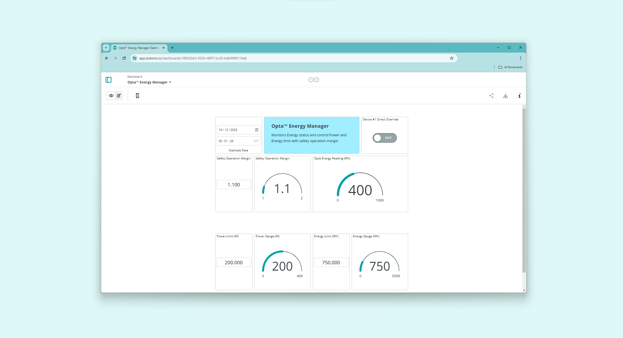
Once set up, you will have the opportunity to design an interface resembling the preview below. This serves as an exemplary dashboard to supervise and control relevant parameters.
Complete Opta™ Energy Management Sketch
Access the complete sketch used in the design of energy management for Opta™ in conjunction with the Arduino Cloud here. The compressed file can be imported directly to Arduino Cloud Cloud Editor for your convenience.
Conclusion
You have built an Opta™ energy manager adept at monitoring an electrical system, evaluating power availability and consumption, and remotely managing devices prioritized by power or energy via the Arduino Cloud.
Opta™ can help manage the energetical balance in industrial environments: in this example, we have considered a scenario where machines can be operated opportunistically, based on power availability, over a 24/7 span, to improve the overall power efficiency.
With a few tweaks, such as integrating different types of power sources, setting varied conditions for machinery operations, and adjusting power-related parameters, this project can be adapted. This flexibility allows for the creation of tailored solutions, addressing numerous scenarios and optimizing energy distribution effectively.
Next Steps
Setting up an energy management system, whether at home or in a industrial setting, can greatly minimize unneeded power usage. Delve into the potential of energy management harnessing the Arduino Cloud to develop a more energy-conscious environment.