Arduino® PLC IDE Setup & Device License Activation
Guide and Tutorial | Arduino® PLC IDE Setup & Device License Activation
Overview
The Arduino PLC IDE offers the possibility to use IEC IEC61131-3 programming languages (LD, SFC, FBD, ST, IL) with the Opta™. The PLC IDE offers a comprehensive set of standard features commonly used in industrial automation.

This tutorial will show you how to connect the Opta™ to the Arduino PLC IDE, learning how to activate the software license and the basic setup to have your board up and running with the Arduino PLC IDE.
Goals
- Set up the Arduino PLC IDE using the Arduino PLC IDE installer
- Download the PLC IDE bootloader to the board
- Establish a connection between your computer and the device using the PLC IDE
- Activate the device license
- Verify the connection between the devices
Hardware and Software Requirements
Hardware Requirements
Board compatible with the Arduino PLC IDE:
The following accessories are needed:
Software Requirements
- Arduino PLC IDE Official Website
- If you have a Portenta Machine Control, you will need a unique PLC IDE License key for your device. Get your license key here.
- If you have an Opta™, you do not need any license key to activate your product. Go to section License Activation With Pre-Licensed Products (Opta™) to know more.
- Arduino IDE 1.8.10+, Arduino IDE 2, Arduino Web Editor or any program with a serial monitor in case you need to retrieve the Hardware-ID of your device.
To get the Arduino PLC IDE and the PLC IDE License for your device, please visit the Software page .
Instructions
To get the Arduino PLC IDE software, go to the official software website of the Arduino PLC IDE and choose to download the PLC IDE installer file. The software is named Arduino PLC IDE Installer.
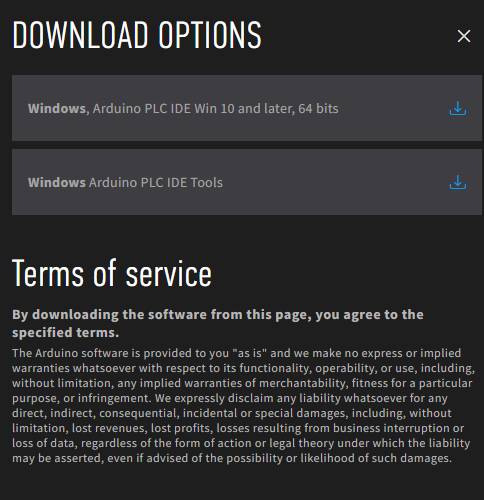
The software requires Windows 10 or a newer operating system version for the x64 architecture.
The Arduino PLC IDE installer contains the IDE and all the required drivers, libraries, and cores. The continuing sections will help you install the Arduino PLC IDE software properly.
1. Arduino PLC IDE Setup
When you download the Arduino PLC IDE installer, the file naming scheme is as follows:
Arduino-PLC-IDE-Installer_X.X.X_Windows_64bit
If you have the correct IDE software, its name should include the version format X.X.X. For instance, a version example might look like 1.0.6. Thus, a complete installer name should resemble the following:
Arduino-PLC-IDE-Installer_1.0.6_Windows_64bit
Run the Arduino PLC IDE installer after verifying that the installer naming scheme follows the above software nomenclature. It helps ensure the software package is legitimate and the latest version available.
During the installation, you may notice several terminal windows opening automatically. These are necessary for the installation process to load all required resources onto your computer successfully, so there is no need to be concerned.
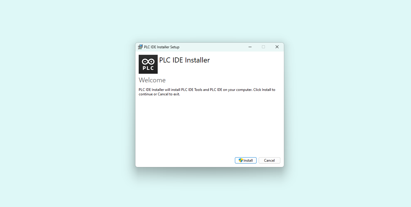
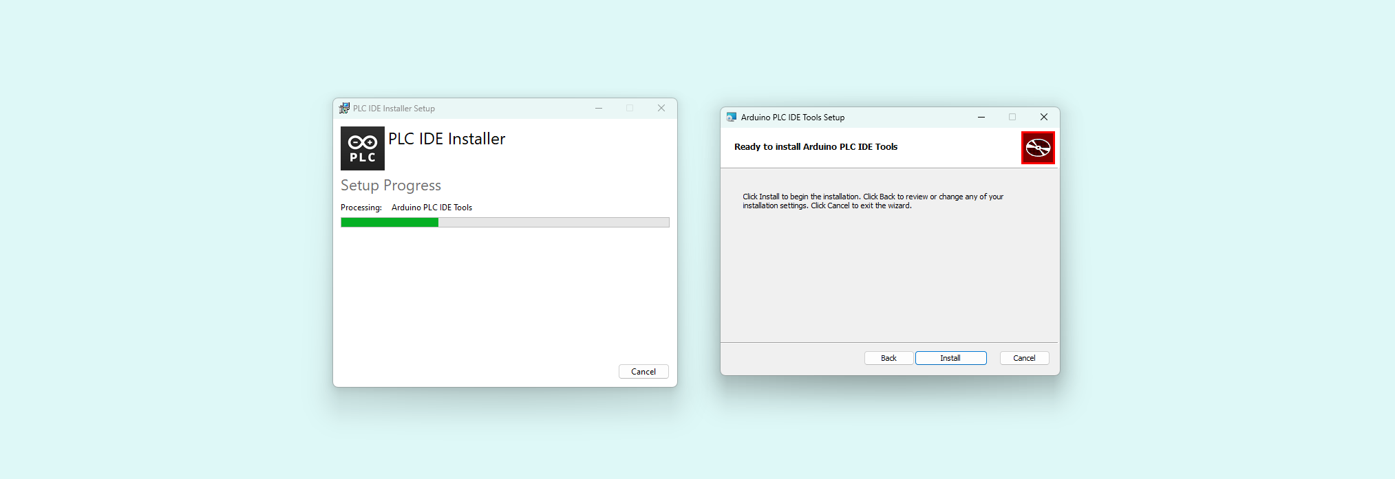
The installation process starts with a window that prompts you to begin. Click Install to proceed:
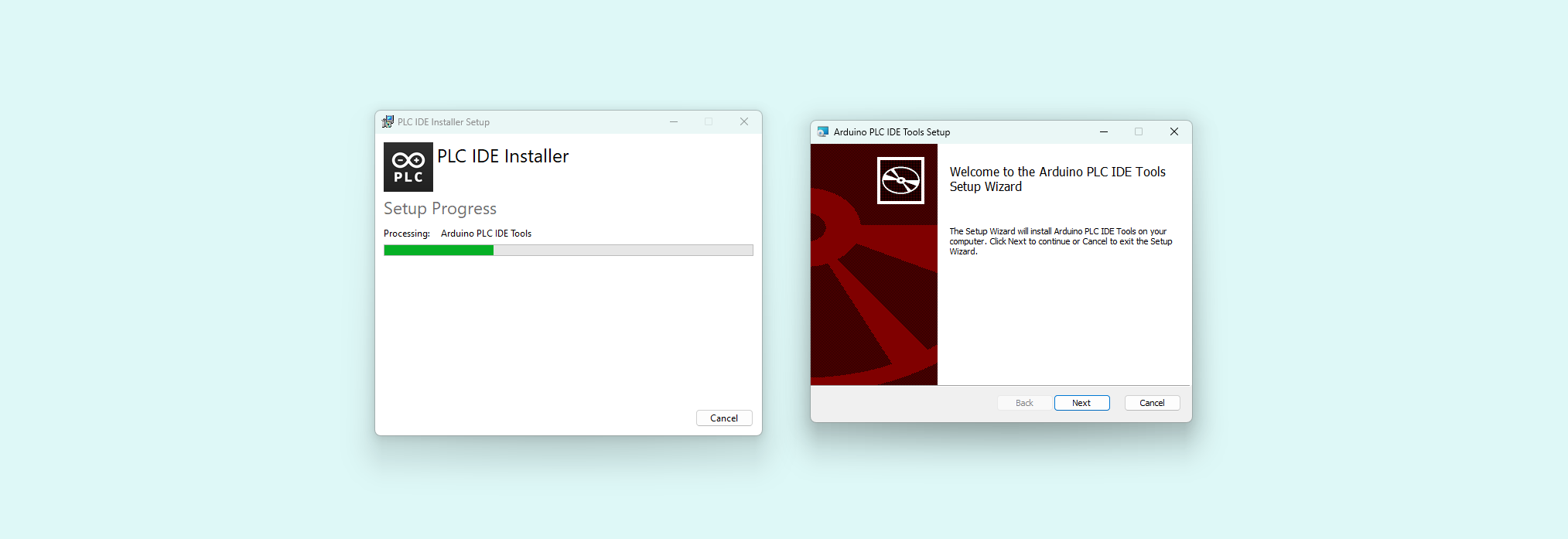
The installation will begin with the PLC IDE Tools. Click Next to continue:
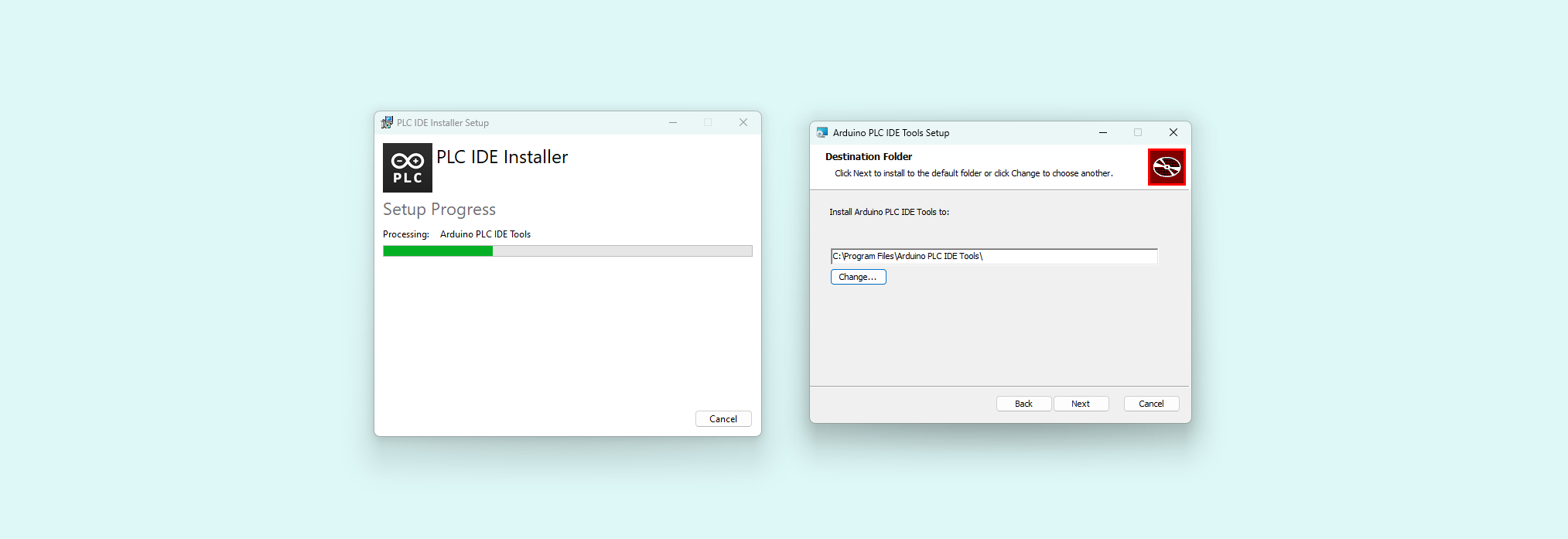
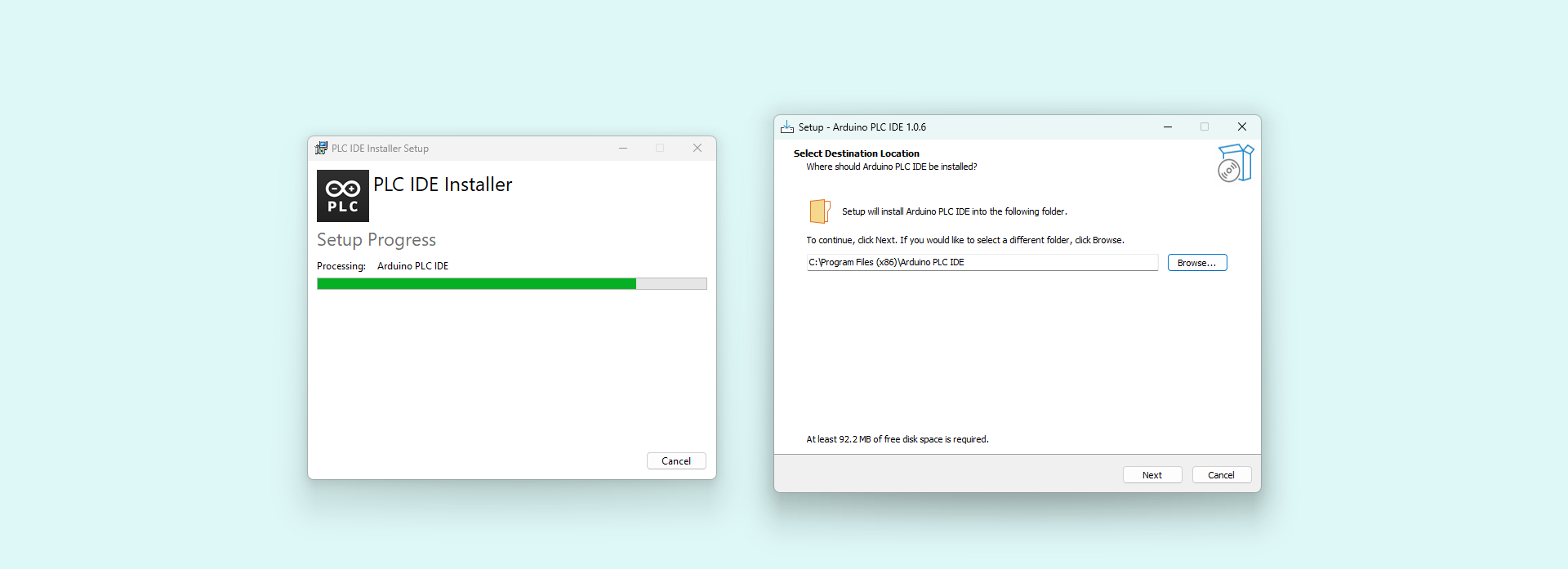
Select a directory for installing the PLC IDE Tools and then click Next:
Click Install to install the PLC IDE Tools in the chosen directory:
Following the PLC IDE Tools installation, set up the PLC IDE software by choosing an installation directory and following the instructions:
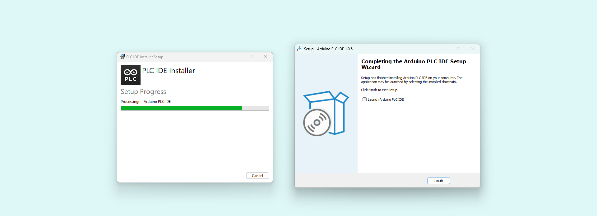
A confirmation window will indicate the completion of the PLC IDE software installation:
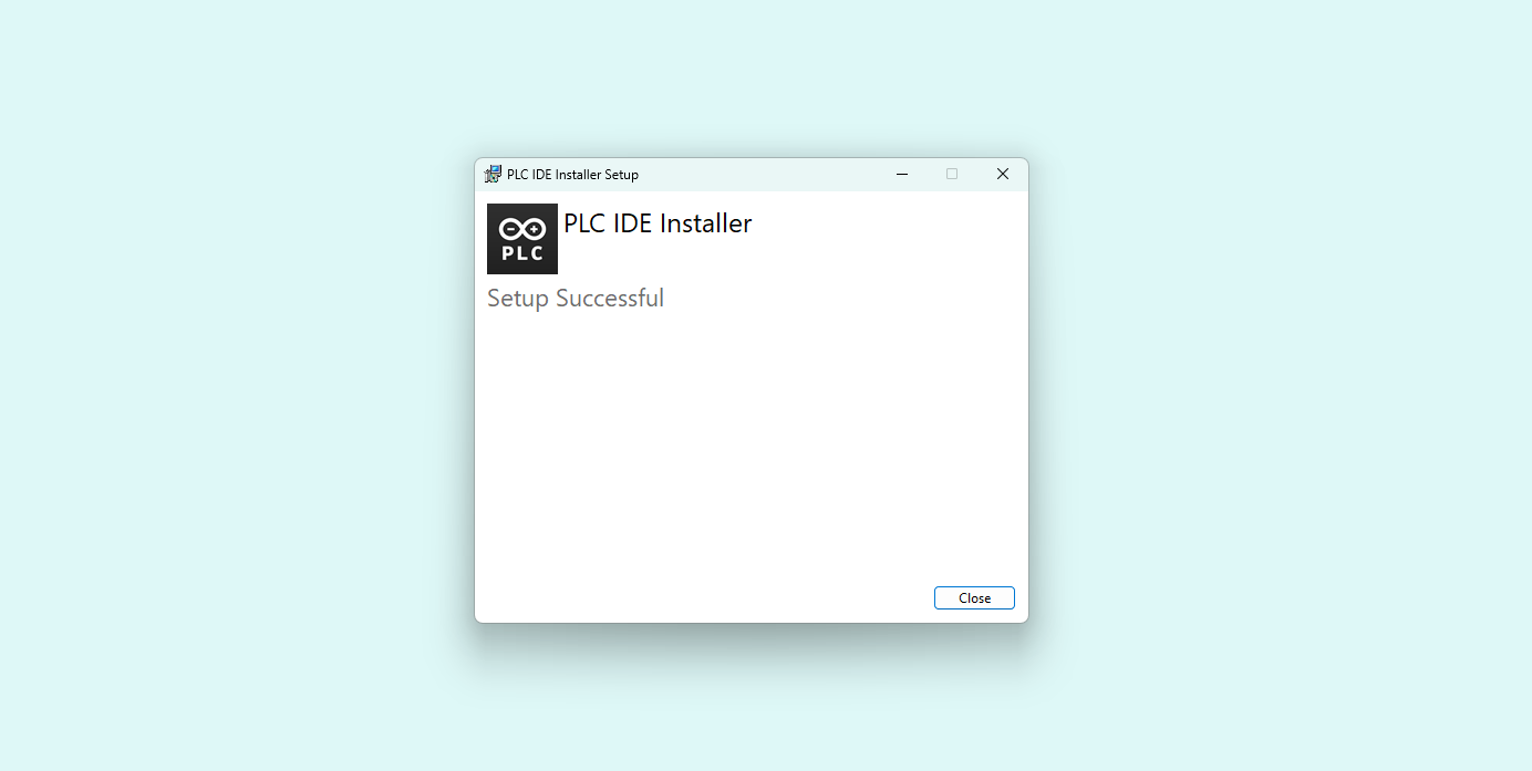
Once the installation is finished, a message will appear confirming the successful setup. Click Close to exit the installer:
If you encounter any issues, restarting your computer can help ensure that all drivers, libraries, and dependencies are properly integrated and updated with the IDE installation.
Open the Arduino PLC IDE program, and the welcome screen will greet you.

The following sections will guide you through creating a project, downloading the runtime, and properly interfacing the Opta™ with its dedicated license activation procedure.
2. Project Setup
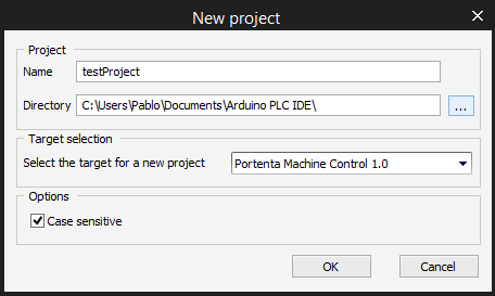
Create a new project by clicking the middle New project ... button or File > New Project.
After creating the project, there are some new windows on the screen; click on the left panel and switch it to the Resources tab inside the window on the tree structure. Now click on your board, it will open the Boards configuration page.
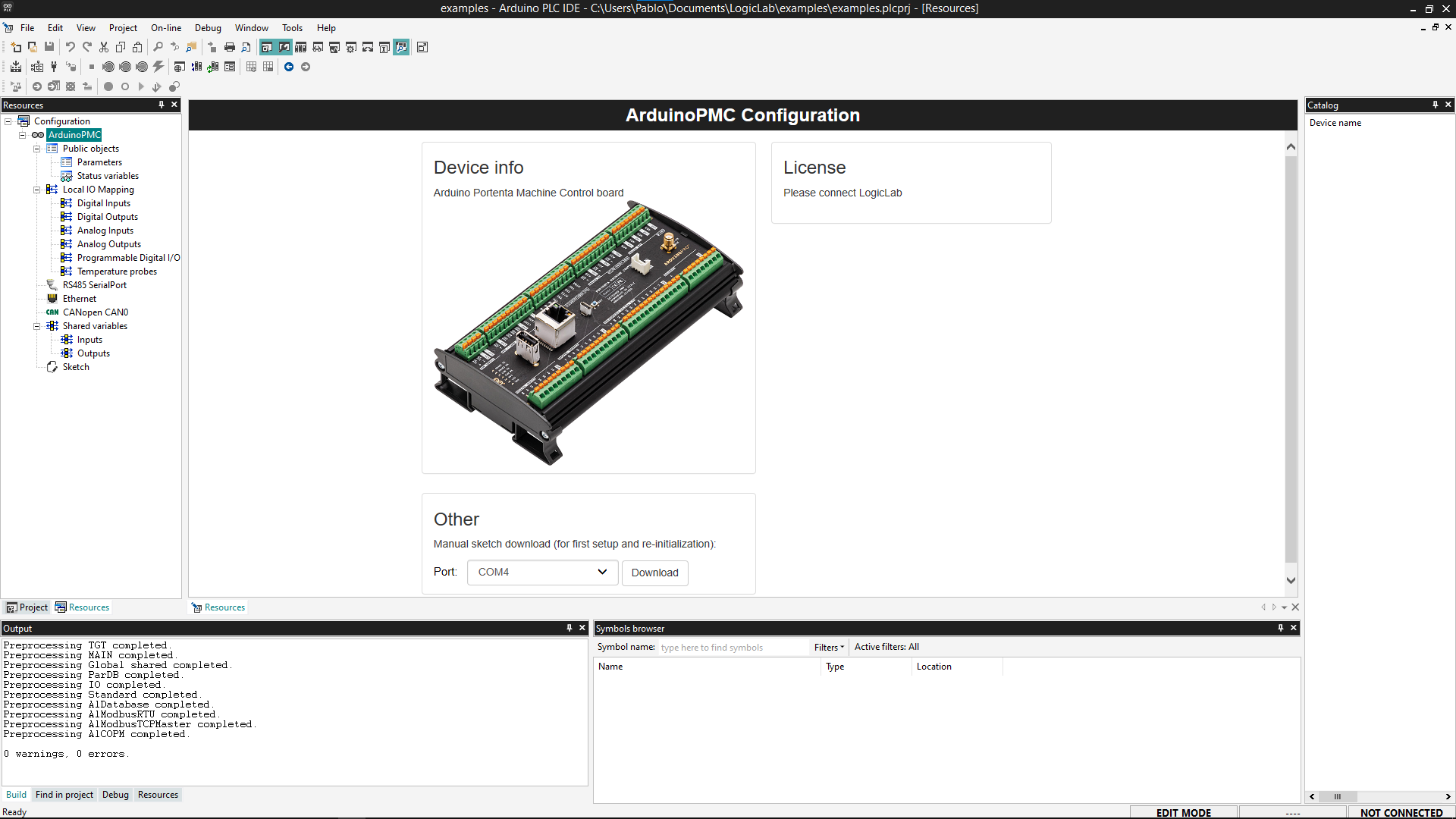
3. Download the Runtime
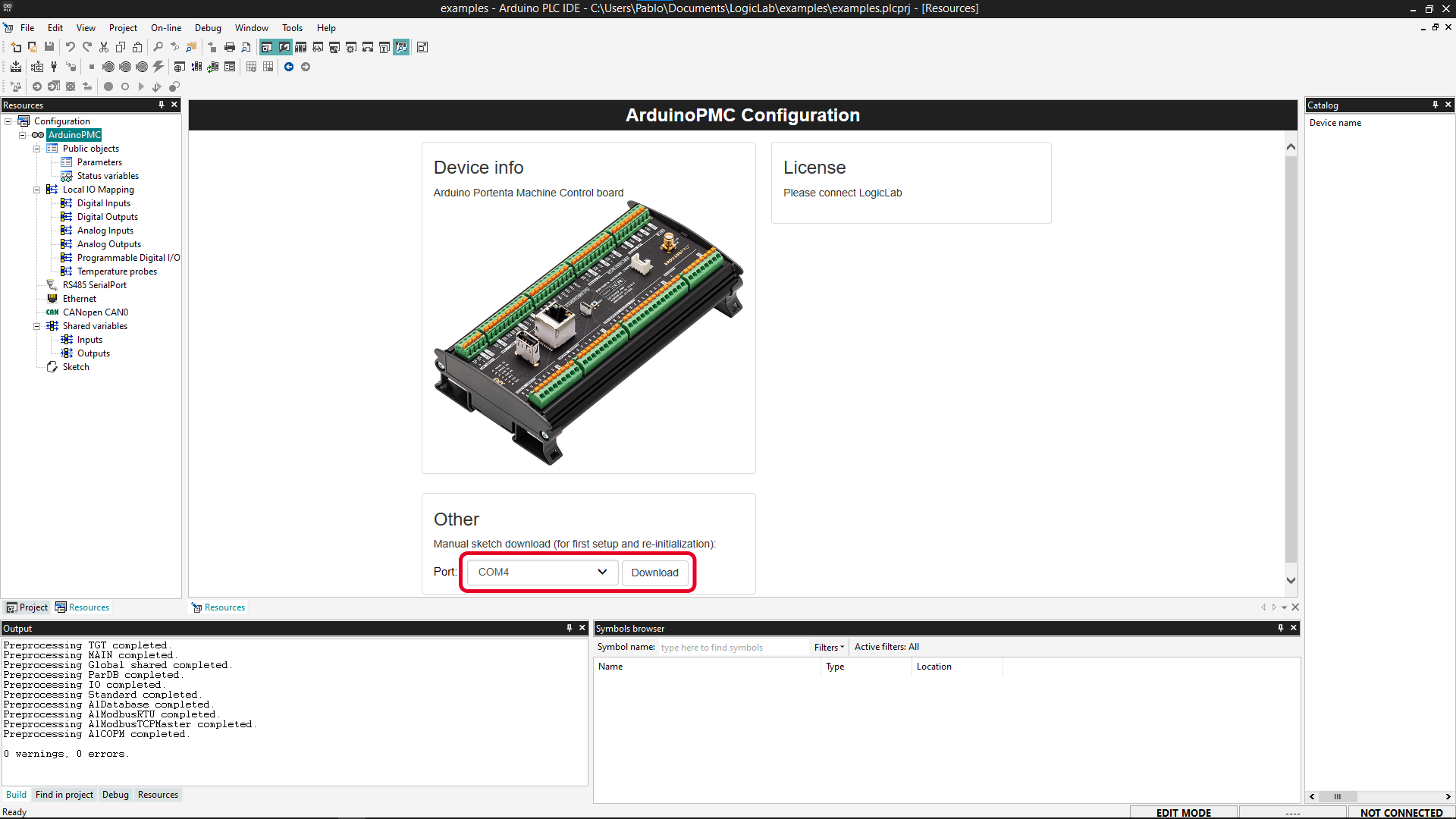
The board needs to run a specific program (runtime) to interact with the PLC IDE. Go to the "Other" section below the "Device Info" block.
Plug your device to the computer, select your board's Serial Port, and click the Download button.
Download the runtime every time you update the PLC IDE from a previous version.
The device will show two Serial Ports: the default (generally with the lowest number) is the usual Serial Port. The secondary one (usually with the highest number) is a virtual port for Modbus communication from the device to your computer. Please take note of the port number assigned to the secondary port (virtual port for Modbus), as it will be needed in a second step.
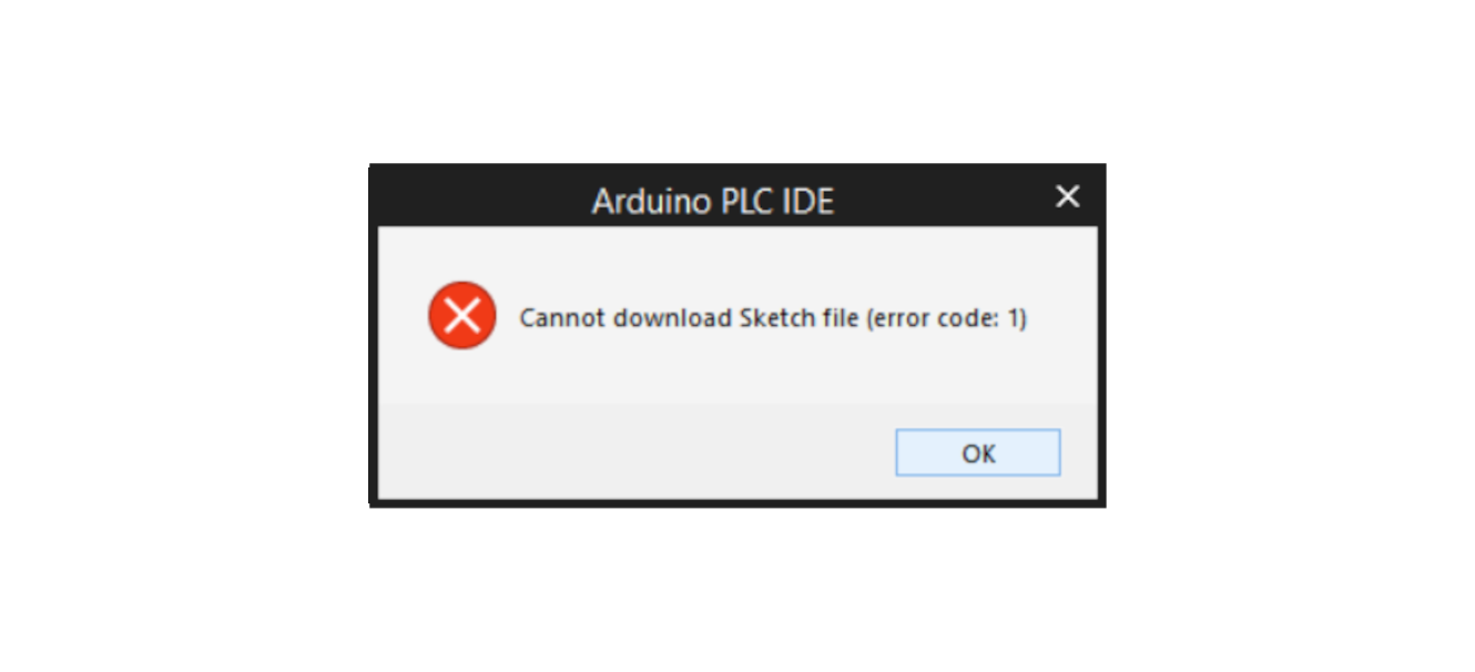
If the following message appears during the download procedure, double-tap the reset button using the tip of a pen or a similar pointed object. The LED above the reset button for Opta™ or the Digital Outputs LEDs for Portenta Machine control will start blinking, indicating that the device is ready to be flashed with new firmware. Click the Download button to begin the process again.
4. Connect to the Device
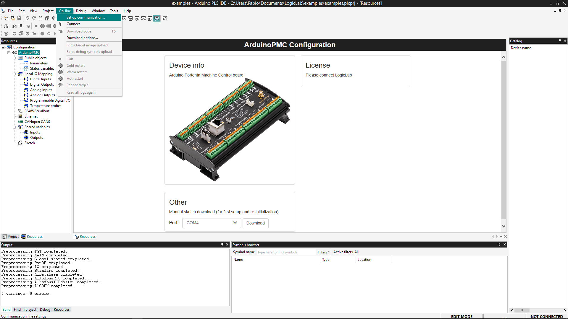
After the runtime is up and running, set up the communication by going to On-line > Set up communication.
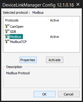
On the new popup window, open the properties of the Modbus protocol.
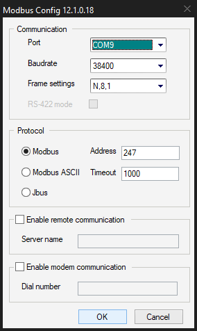
Ensure the Modbus protocol uses the secondary Serial port number, the Modbus Virtual port you noted before. Press OK.
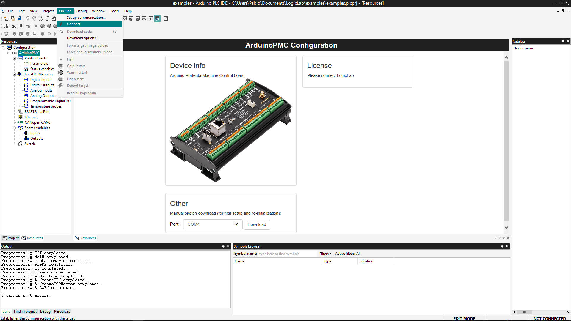
Click OK to save the settings and press the connect button on On-line > Connect.
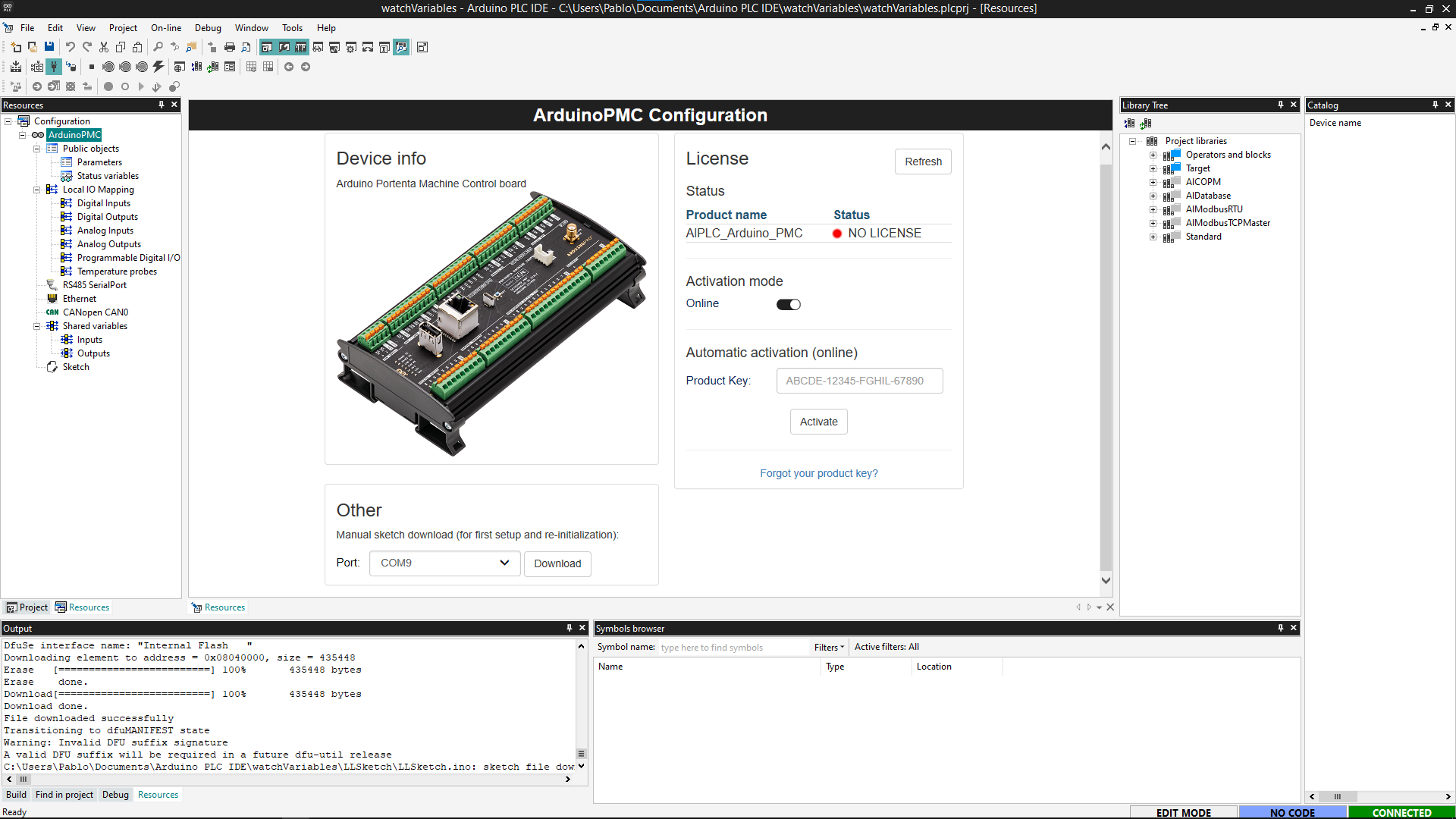
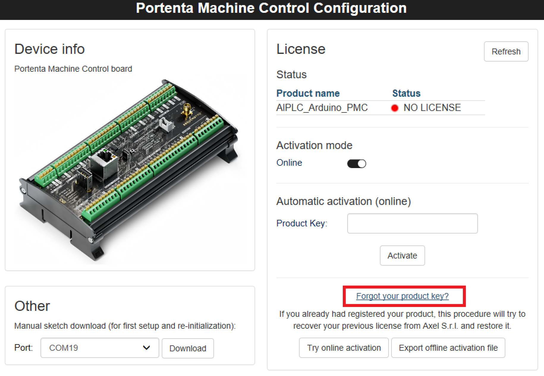
5. License Activation with Product Key
If the communication is successful, the main panel will show the license section to be filled in and a status indicator.
Online Activation
To use your product license, paste the key in the blank next to Product Key and press the Activate button.
After you click the Activate button, the IDE will bind the license to the hardware ID. A popup telling you to reboot the target (which is the device connected to the PLC IDE) will show up; press the reset button of your device to reboot.
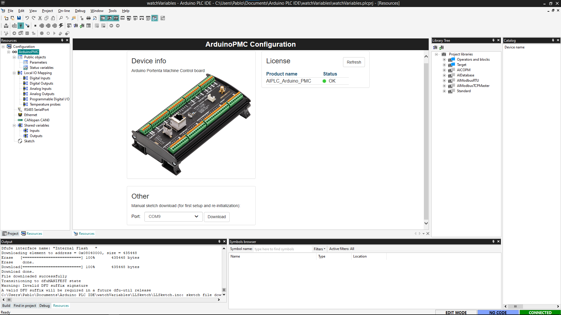
Once the product has been activated, getting the Hardware-ID of your device is recommended.
Offline Activation
To activate the product Offline, deselect the "Online" slider, and the scenario below will show up:
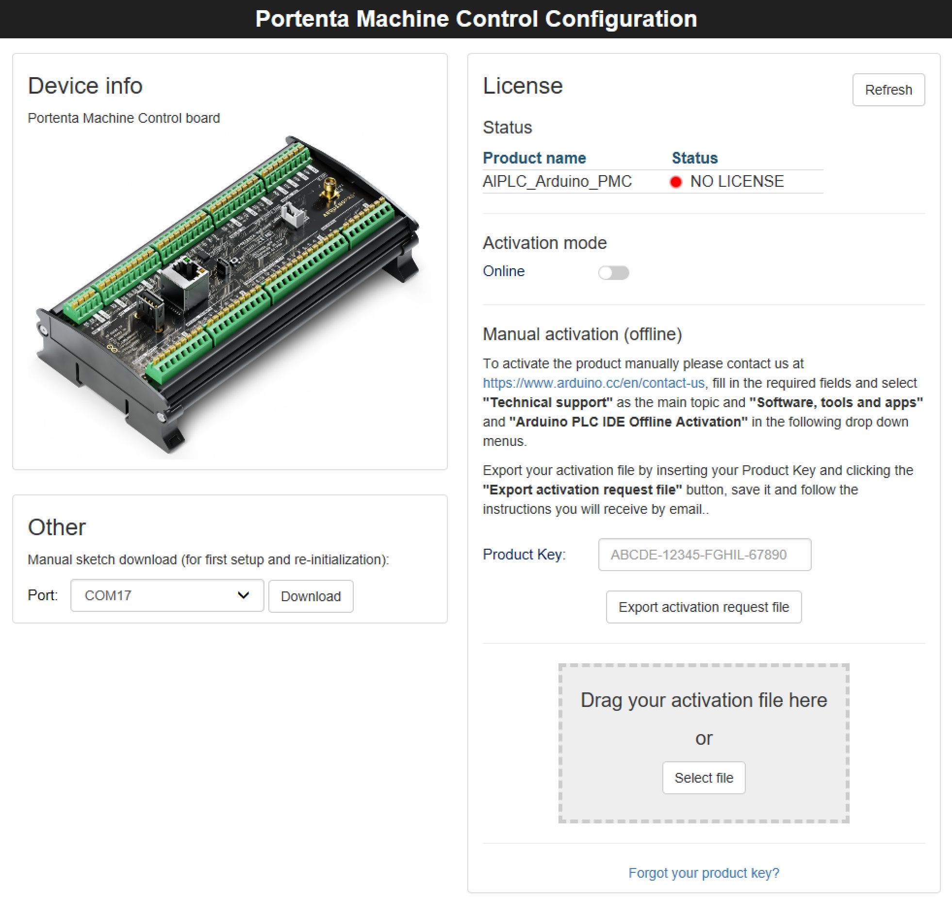
Follow the instructions provided using our Contact form and generate the Activation Request File.
Once you receive the Activation file, drag and drop the file in the dashed rectangle or select it from the folder where it is stored to complete your Offline Activation.
6. License Activation with Pre-Licensed Products (Opta™)
When a product is Pre-licensed, the following scenario will be displayed:
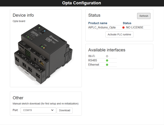
Make sure your device is already connected to the computer and click the Activate PLC Runtime button, the product activation will be completed, and the PLC Status will be set as OK:
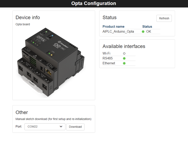
Now, the product is ready to be used with the PLC IDE.
7. Activation Recovery
In case the hardware is being reflashed and the key got lost, the license can be recovered just by clicking the "Forgot your Product Key?" button:
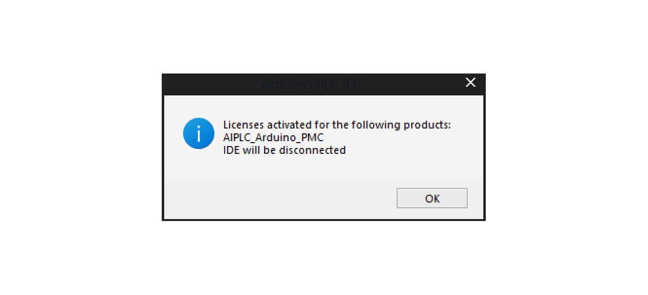
The IDE will then connect to a server, validate the hardware, and recover the activation, showing a confirmation popup when done:
8. Getting the Hardware-ID of Your Device
The hardware ID of your device is an important number to save in case you have problems with the divide or your PLC IDE license. To get the unique Hardware-ID of your device, follow the next steps:
- Be sure that your device is disconnected from the Arduino PLC IDE
- Open the Arduino IDE software
- Go to Tools > Board > Arduino Mbed OS Portenta Boards > Arduino Portenta H7 (M7 Core)
- Go to Tools > Port to select the proper port (the default one shown before in the PLC IDE inside the Arduino PMC Configuration > Other section)
- Go to Tools > Serial Monitor and reset the board. Look at the end of the boot report to find the "Hardware-ID" and store it in a safe place.
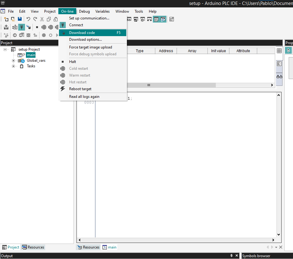
9. Download a Program
Let's download and run the first program on your device. We are going to use the default program that is included in a project: a counter.
Double-click on the file main inside the Project to see the counter program. To download that program to your PLC, you must compile it and send it to the target device.
10. Communication Test
Open the Watch window by clicking "View > Tool Windows > Watch". It will attach a new window on the right side called Watch. This window shows the real-time variables value.
To add a variable to be watched, click the Insert new item button inside the window. It will open a popup window; on the name label, insert "cnt" and click OK on the location "main". It will add the variable cnt from the main program on the table or drag and drop the cnt variable from the Project tree or from the Main program.
Select the Watch window and click on the Start/Stop watch button unless the variable's value is already getting updated.
Conclusions
In this tutorial, we went through how to set up the Opta™ with the Arduino IDE lab, learned how to connect the board to the program through Modbus, activate the hardware license of your product, and create a simple sketch with one variable that went compiled and downloaded inside the board. Finally, we learned how to see the values of the variables in real time using the Watch window.
You can create professional solutions now that your board is running with the Arduino PLC IDE.